
ArtMatic Voyager CTX References
Interface Basics & Conventions
Section titled “Interface Basics & Conventions”Almost everything that you can see in the user interface is active, including the text, icons and glyphs. Pretty much every graphic item can be clicked or dragged to perform a task. Like all U&I Software applications, most tools are accessible directly from the user interface.
Numerical controls and slider:
Section titled “Numerical controls and slider:”Numeric controls allow you to change values by typing or by clicking and dragging. When typing, complete entry by pressing return or entry key. Selecting another field should also validate the entry. You can change the number with smaller increments when pressing the option key while dragging a slider horizontally or a number field vertically.
Shortcuts:
Section titled “Shortcuts:”*(times 2) changes the field value to twice its value/(divide by 2) changes the field value to half its valuei(invert) changes the field value to 1/value ,d(degrees) interpret the entry as degrees converted to radians and shall be used at the end of keyboard entry. for example to get exactly Pi type 180 thend. d should validate the entry automatically.
Color Pickers
Section titled “Color Pickers”Color swatches allow you to change items such as the sun and sky color. Click and hold a swatch to pop up the color picker. The cursor becomes an eyedropper that picks up the color beneath it when the mouse is released which makes it easy to grab color from anywhere in the background. Unfortunately Apple in recent OS makes the reading of screen pixel subject to Authorization so you will have to grant Voyager the right to access the screen otherwise the color picker won’t work. Keep in mind the picker can read any color anywhere on the screen which is extremely useful as you can pick a color from a picture unrelated to Voyager on the desktop for example.
Inspectors and Dialog
Section titled “Inspectors and Dialog”Introduced in Voyager 5 Inspectors allows to edit deeper settings in a non modal way unlike dialog. Thus we keep the name “dialog” for modal windows that prevent main UI to operate while we use “inspector” for UI that pops up in certain areas but don’t prevent controls, menus and main preview to be functionnal. The most important UI tools to control objects, sprites, lights, animation, render options and environment controls have been reimplemented as “inspectors”.
Inspectors will appear on the side without hiding the main view. The main UI that control the Camera, Environment and Positions is still accessible while using a specific inspector. Modeless “inspectors” are used for Objects, Sprites, Lights, Animation and deeper Environmental options and parameters.
They can be opened using the icons on the top right of the UI. The one specific to timeline ‘Animation parameters’ is located in the timeline area. Some functionality that were in the dialogs were moved to the main UI because the non-modality make them usable even when a particular “inspector” is open. For example a new section ‘Positions’ below the ‘Camera’ handle the positioning of every elements in a VY scene which meant the position slider became redundant in the dialogs.
‘Positions’ can apply to objects, lights, clouds, textures and even the main planet terrain. In general the target will be set automatically when selecting an object or a sprite or a terrain but you can use the mode pop-up at the left of the section to decide to move the cloud layer, even if you are placing sprites or objects at the same time. So practically if you open the object inspector to import various objects you can still move the sun or change the camera view.
Keyboard entries can’t be assigned to several windows simultaneously. Thus a selection click is needed on Main UI before keys input can be redirected to it when an Inspector is Open. Likewise click on the Inspector area to redirect keyboard entries to the inspector.
Adaptative resolution
Section titled “Adaptative resolution”Most of all sliders gives you real time preview at an adaptive resolution. You can click and drag on any control while seeing in real time the result of camera or object changes. When the scene is slow this real time preview will be at a very low resolution but enough to have a useful feedback. As soon as you release the mouse a better rendering is starting, a rendering that can be interrupted at any moment to tweak another parameter.
Context variables
Section titled “Context variables”ArtMatic Voyager provides you with a great deal of control over the planet’s environment. The light, haze and other environmental parameters can dramatically change the planet’s appearance. Most of the environmental controls are found in the lefthand toolset and in the Environment settings dialog. The environmental variable with the camera and the built-in lights constitute what we will call the Voyager Context variables.
It includes:
- Camera location and view direction,
- Sun Direction & color – The sun’s position & sun color,
- Ambient level – controls amount of incidental/ambient light available,
- The Wetness level – controls degree water and low elevations reflect the sky color,
- Haze and the Haze Color picker – controls environmental haze,
- Sea level & sea color – sets the altitude and color of the global planet ocean,
- Sea Roughness (slider) – influences the wind speed (and thus the motion of clouds when a system is animated),
- Snow – sets the altitude at which snow will be automatically added,
- Built in lights providing additional suns and/or light sources,
- Clouds density, size & position,
- Sky Environment rotation or position for backdrops,
- Illumination gains and Gamma filter.
Context variables can all be animated as each Voyager Keyframe will store a copy of the entire Context. You can disable the animation of a particular variable with the Animation Parameters inspector. Note that Planet mode and Sky mode and some global settings (Mist, Atmospheric color shift, Underwater color shift and various rendering modes) are NOT part of the context and can’t be changed while animating.
Context variables are stored in places as well. You can use the main Edit menu to copy and paste the entire context or choose to replace only part of it using “Paste Context Camera” or “Paste Context Environment” menu items.
Learn more about environment variables here
Sprites inspector
Section titled “Sprites inspector”Keyboard Shortcut: x

Opens the Sprite inspector. Sprites are very fast to render and can provide a lot of cool visual effects for animation when using animated ArtMatic systems: meteorites that cross the sky, various light effects, even reflective water flakes. Static PNG sprites can be used to add people in your architectural or landscapes scenes, a city in the background, or some trees in the foreground etc…
The Sprite inspector gather all tools to open, scale, orient, activate and shade sprites. You can use the main Sprite menu to copy and paste sprites between different voyager scenes.
DF objects inspector
Section titled “DF objects inspector”Keyboard Shortcut: o

Opens the the Objects inspector. The objects inspector gather all tools to open, scale, activate and shade DF 3D objects.
You can use the main Edit menu to copy, add or paste objects between different voyager scenes.
Lights inspector
Section titled “Lights inspector”Keyboard Shortcut: l

Opens the Lights inspector. The Lights inspector gather all tools to setup and shade built-in additional lights. Lights are fully animatable and can be treated as additional suns so Voyager CTX can have multiple-sun worlds. Lights positions and settings are context-dependent so places and keyframes can have different lights.
ArtMatic params & shaders
Section titled “ArtMatic params & shaders”
Opens the ArtMatic parameters & shaders inspector for Quick Editing within Voyager (a deeper ArtMatic Tree editing requires using ArtMatic Designer). This inspector gives you a direct access to “Published” parameters from the selected tree and can set the shading options associated with Extra Outputs.
As ArtMatic trees are used for many things in VY you have (on the top-right of the inspector the wheel-gear icon) a dynamic popup that lets you choose which tree you want to modify. You can also rename the tree which is often useful after modifying an existing one or to create variations.
Environmental Context
Section titled “Environmental Context”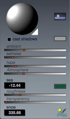
The tools on the left hand side in the ArtMatic Voyager UI are dedicated to Environmental control variables that are part of the current Context variables.
Sun direction sphere
Section titled “Sun direction sphere”The sun direction sphere allows you to set the position of the sun that illuminates the planet. The sun’s angle realistically influences the color, the shadows, and reflections. Click on any point to focus the sun’s light at that point. The bright spot indicates the sun’s position relative to the planet’s sky dome, which is represented by the sphere. When the illuminated spot is in the center of the globe, it is noon (i.e. the sun is directly overhead). When the illuminated spot is at the edge of the globe, the sun is dipping towards the horizon. In Voyager 5 it is possible to put the sound below the horizon. In no planet mode, this allows for the sun to light objects from below.
Sun color box
Section titled “Sun color box”To change the sun color, click and hold the sun color rectangle to pop up the color picker. Sun color affects all colors in the scene and the clouds. The sun provides directional lighting and is the primary source of illumination whereas the Ambient slider provides diffuse non-directional lighting. To decrease the sun’s contribution to the lighting, lower the brightness of the sun color. If you set the sun color to black, the ambient light from by the sky and the haze will provide the scene’s illumination and shading. Varying sun color along with the haze color and sun position allows ArtMatic Voyager to simulate a wide variety of light conditions.
Sun/Atmosphere mode pop up
Section titled “Sun/Atmosphere mode pop up”Sun/Atmosphere pop up menu is located to the right of the Sun direction sphere. It will set various aspect on how the atmosphere and sun are rendered.
The modes are as follow:
Sharp sun:
Section titled “Sharp sun:” The default mode with a sharp disk rendering of the sun.
Strong halo, (fuzzy sun, red shift):
Section titled “Strong halo, (fuzzy sun, red shift):” Atmospheric halo is stronger in this mode which includes red shift scattering when the sun is low on horizon.
Extra bright sun, (red shift):
Section titled “Extra bright sun, (red shift):”
The sun is rendered as a smaller but brighter point and the mode includes red shift scattering when the sun is low on horizon.
Soft halo, no sun:
Section titled “Soft halo, no sun:” A softer halo around an un-rendered sun. This mode is suited for use with ArtMatic 360 or ArtMatic Backdrop sky modes.
No halo, no sun:
Section titled “No halo, no sun:” The no halo, no sun option is often desirable when using the ArtMatic 360 or ArtMatic Backdrop sky modes, in particular when the ArtMatic Environment systems already shades the sun with an alternate representation. For example you may have a sun with rays and a rainbow ring around. The Voyager Skies library provides many example of custom skies shaders.
Automatic with scattering:
Section titled “Automatic with scattering:” Introduced in version 5, this sky/sun mode offer a more realistic approximation of atmospheric scattering. It has red shift when sun is low and the haze color tends to be less pronounced and more realistic because haze is sensitive to scattering direction. The sun is rendered like in ‘extra bright sun’ mode. Note that Atmospheric scattering hue can now be changed to non-oxygen worlds in the “Environment settings” inspector.
Cast shadows
Section titled “Cast shadows”When this option is on, the surface will cast shadows on itself, and any clouds will cast shadows on the ground. This greatly increases the realism of the scene (and also rendering time). This setting is ignored in Draft quality.
Computing shadows is computationally intensive and turning this option on can cause rendering to take many times longer than when it is turned off. Terrain self shadows have been improved in ArtMatic Voyager CTX 1.5.
The render quality setting affects the accuracy of the shadows. When the setting is better or best or sublime, Voyager uses very refined sampling which can take a long time, but will yield the very best results. You may want to start with good quality and increase the quality if the shadows seem wrong or incomplete.
Haze slider & haze color
Section titled “Haze slider & haze color”The haze setting determines the amount of atmospheric haze (caused by moisture and suspended particles in the air). With low values, the haze is only visible at a distance. With high values, visibility is reduced dramatically. The Atmosphere Height preference also affects the density of the haze and determines how high the haze will go. The haze color can be changed by clicking (and holding) the mouse on the Haze Color picker.
ArtMatic Voyager models the scattering of light that causes a blue shift of dark colors and red shift of bright colors that increases with distance. Changing the haze color has a dramatic impact on the way that colors are attenuated and shifted in the distance. Setting the haze color to gray enhances the red shift. In ArtMatic Voyager (just as in reality), a low sun will appear more red than it is.
As ArtMatic trees are used for many things in VY you have (on the top-right of the inspector the wheel-gear icon) a dynamic popup that lets you choose which tree you want to modify. You can also rename the tree which is often useful after modifying an existing one or to create variations.
Ambient Slider
Section titled “Ambient Slider”This slider controls the amount of ambient light provided by the diffuse scattering of light from the sky dome. The ambient light is an overall illumination predominantly provided by the sky when in Automatic mode and is non-directional (unlike the sun’s). When ambient light is strong, the colors of the sky will “bleed” noticeably on the surface. Ambient light can be eliminated by setting the slider to its minimum value (0). Without ambient light, areas that are not directly lit by the sun will be very dark.
The Ambiant slider affects the level of ambiant for all objects and terrains in the scene. Objects and sprites have their individual ambiant level and the maximum is taken between the gloabla and particular ambiant level value. The Environment settings inspector offers five options for the ambient light mode:
- Automatic: Automatic is the mode used in ArtMatic Voyager 3 and earlier. The ambient light is a blurred low-res image (128*64) derived from the scene’s environment map and is recalculated for each frame. The object or terrain normal set the location in the ambiant map.
- Image: When you use an image as the light map, it is resized to
128px * 64pxand blurred. The image is stored in the Voyager scene’s bundle asAmbiantMap.png.
The object or terrain normal set the location in the ambiant map. - Image+Constant: A constant color derived from various environment color is added to the chosen image.
- Constant: Constant mode uses a mix of the sun, haze and sky color to create a uniform ambient light.
- Constant white: Introduced in Voyager 1.5 “Constant white” provides an uniform non directional white light. It is often used with Balance light energy activated so that the role of ambiant is stronger and neutral.
Wetness slider
Section titled “Wetness slider”This setting determines how much the sea and snow and areas near the shore reflect the sky color. It also accentuates the water’s reflectivity. When the wetness is high, you get fuzzy specular reflections in the areas affected by the setting. It also may change 3D object wetness as the renderer takes the maximum of the global wetness setting and the object own wetness setting.
Atmosphere height slider
Section titled “Atmosphere height slider”The Atmosphere Height sets the altitude at which atmospheric gases becomes insignifantly small. It affects the density of the haze and determines how high the haze will go and how much scattering is going on in the sky shading model. The slider range is between 1 meter and 8000 meters.
Sea level & Sea color
Section titled “Sea level & Sea color”Sea level determines which elevations are filled with water. It is expressed in meters. Everywhere below sea level will be covered with water. Use the color picker found next to the slider to choose the sea color.
In scenes where most of the sea color comes from the reflection of the landscape and sky, use a dark color for the sea since the sea color is added to the total light coming from the water and can easily get too bright if its color is too light. The sea color is also modulated by the depth of the sea. It is darker where the water is deeper.
Sea Roughness Slider
Section titled “Sea Roughness Slider”This slider controls the surface texture of the sea by controlling the wind speed which makes the sea rough. The wind speed also affects the cloud movement speed. Clouds move automatically when time flows. Roughness influences the sea reflectivity and usually the amount of foam as well. Rough seas are less reflective than calm sees. The sea appearance can be modified with the various options available in the Environment settings inspector .
Transparency slider
Section titled “Transparency slider”This slider controls water transparency. The appearance of underwater features is also influenced by the Underwater Color Shift setting in the “Environment settings” inspector .
Snow Level
Section titled “Snow Level”Snow level determines the elevation above which the planet terrain is covered by snow. The amount of snow is influenced by the steepness of the terrain and the elevation above snow level. The range is from -500 to 10,000 meters. You can generally eliminate snow by setting the snow level to 10,000 meters since it is rare that you will have peaks that high.
Environment Settings…
Section titled “Environment Settings…”
Opens the Environment Settings Inspector.
The inspector provides higher precision sliders and numeric fields to set parameters that are often present in the main UI. For example you can set the sun direction more precisely than with the sun ball controller.
It gathers Context variables and global scene parameters that are independant of places and keyframes like the “Atmospheric color shift”.
Some rendering modes (ambient light) or sea behaviours can be adjusted in there as well.
Atmosphere and clouds :
Section titled “Atmosphere and clouds :”- Sun direction vector – Sets the Sun direction numerically. Note that the final vector is normalized internally,
- Haze
- Haze color – Color picker to set the haze color,
- Atmospheric color – Color picker to set the limit color of atmospheric scattering. It can be more or less saturated and hue shifted. Luminosity has no effect,
- Atmospheric color shift – Sets how much hues are shifted by the atmosphere in the distance. The sky color is sensiive to this setting,
- Atmosphere height – Sets the atmosphere height in meters,
- ArtMatic clouds scaling – Picker to choose between Absolute and keyframed scaled clouds,
- Cloud Density
- Cloud Size
- Mist top altitude (meters) – This global scene parameter sets the altitude at which mist vanish,
- Mist range (meters) – This global scene parameter sets the height of mist. Below Mist top altitude - Mist range the mist is very dense. Note that the mist level is further modulated by the haze amount.
Ambient Model:
Section titled “Ambient Model:”- Ambiant modes – See Ambiant slider for more information
- Open image – Use this button to load your own ambient image maps.
Water and Sea Models:
Section titled “Water and Sea Models:”- Waves picker – Set the type of sea waves.
- Foam picker – Set the sea type of foam. You can disable foam whatsoever using “never”.
- Water roughness / Wind
%– This context variable sets the wind speed and hence the sea roughness. It affects the speed of built in clouds as well when animating. - Water transparency
%– This context variable sets the sea transparency, - Sea level (meters) This context variable sets the sea level,
- Underwater color shift – Color picker to set the limit color of underwater absorbtion,
- Copy to all places – This button duplicate the environment setting to all recorded Places. It is useful in particular if you need to force Context variables to be identical in every Places.
Main View area
Section titled “Main View area”The main view area is not only the place you will preview the current scene. It can act as a controller as well if you click and drag on it to move the camera. The amplitude of the motion depends on the Map Scale radius. The resolution of the preview is adaptative and will change to allow quasi realtime feedback when sliding parameters or previewing animation. Many single shots commands display a low res preview before starting a finer calculation.
Planet And Sky Settings
Section titled “Planet And Sky Settings”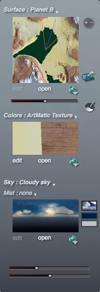
The tools on the right hand side of the ArtMatic Voyager UI provides most of the controls for setting up a scene:
- The Surface that defines the planet,
- The Texture that shades the planet and the Sky settings that handle sky rendering.
Various UI elements and sliders may appear depending on the chosen modes for Skies and Textures.
Map Overview
Section titled “Map Overview”The surface map shows the portion of the planet that surrounds the current camera position. The default dimensions of the area covered by the map can be set with the Map Scale (radius) button below. The map reflects the current sea and snow level settings as well as the surface color mode. Click and drag on the Map Scale controllers to zoom in or out on the map. The red lines indicate the view visible at the current zoom setting. The blue line indicates the current compass heading.
Click on the map to move the camera to clicked location. You can also click AND drag while keeping the mouse down to move the camera on the Map: the main view will render the camera view in fast preview mode interactively.You may even go outside the Map area while dragging which gives you a much larger virtual region to explore. This offer a very efficent way to position the camera.
If you want the Camera to automatically stay near the ground, set the “snap to ground” preference to ON whilst using the Map to position the camera.
Map Scale
Section titled “Map Scale”(radius in km)

Click on the Map Range control, and drag left or right to increase or decrease the visible area in the “Map overview”. You can zoom in to see fine details of the landscape or zoom far out to get an overview of the planet’s terrain.
As you drag the mouse, the Tool Tips area at the bottom displays the dimension visible in the map overview. Large ranges (100 km. or more) are useful for seeing large-scale features and to facilitate large location jumps (by clicking on the Map overview). Smaller ranges are useful for fine camera adjustments, or to navigate inside a DF volumetric city.
The default range of the map will define the parameter range for various relative camera sliders, as well as the amplitude of motion when clicking/dragging in the main view.
Surface mode pop-up
Section titled “Surface mode pop-up”Use the Surface mode pop-up menu to choose a planet surface. You can use one of the built-in planet models, an ArtMatic file, or combination mode allowing several ArtMatic systems to be combined with each other, and/or a built-in planet. Many examples of various types of terrains are provided in /Voyager Examples/Terrains & Landscapes/ folder.
Surface Modes:
Section titled “Surface Modes:”-
Planet A:
Section titled “Planet A:”Built-in planet A has a lot of small scale variations that result in dramatic changes over short distances. On a large scale, this planet tends to repeat itself and does not have very high mountains nor the large oceans of Planet X or Planet C . It is quite fast to render as its model is the simplest of all.
-
Planet B:
Section titled “Planet B:”Built-in Planet B has larger-scaled features than Planet A. Planet B often displays Nevada-like wide valleys with lovely rock clusters and high surrounding mountains. Terraces and steep canyons alternate with rocky shorelines and lake- filled valleys.
-
ArtMatic surface:
Section titled “ArtMatic surface:”This mode uses an ArtMatic file to define the planet geography with animation disabled. The planet’s terrain will be defined entirely by the ArtMatic tree using the current parameter values. Learn more about ArtMatic Surfaces design.
Examples in:/Voyager Examples/Terrains & Landscapes/ArtMatic Terrains/ -
ArtMatic animation:
Section titled “ArtMatic animation:”This mode uses an ArtMatic file to define the planet geography with animation enabled. The planet’s terrain will be defined entirely by the ArtMatic tree using the current parameter stored in the keyframes. The time slider will then animate the terrain provided the keyframes have varying parameters.
-
Planet X:
Section titled “Planet X:”Planet X has larger features than planets A and B. It may require traveling 500 km for the landscape to change dramatically. Large oceans and high-altitude plateaus alternate with rough shorelines, gently rolling hills, rocky deserts, lake and river districts, sand dunes, rock fields and large mountain ranges.
-
Planet C:
Section titled “Planet C:”Planet C is the most sophisticated planet algorithmically and has the largest scale features of the built-in planets. More diverse and geologically realistic than the others, Planet C features large oceans, huge beaches, stratified canyons, sand dune deserts, river systems, faults and huge parallel mountains ranges. The highest peak can be over 10 000 meters.
-
Planet D:
Section titled “Planet D:”Planet D is a planet with diverse topography that includes beaches, deserts, grasslands, and polar ice caps.
-
Combination:
Section titled “Combination:”Combination Mode allows you to modify the main planet (which can be either a built-in planet or an ArtMatic file) with up to 6 ArtMatic files. The ArtMatic files can be combined in many different ways with the main planet.
See how to build a planet using Combination mode. Examples in:/Voyager Examples/Terrains & Landscapes/Combination scenes//VY5 Combination/
-
No Planet:
Section titled “No Planet:”The ‘no planet’ mode completely removes the terrain and the atmosphere and is suited for deep space scene, often using a 360 environment map sky mode.
Elevation gain
Section titled “Elevation gain”The Elevation gain slider controls the surface amplitude which acts as a multiplier to the elevations found in the planet’s source definition. Setting the amplitude high exaggerates surface features. Setting the value low flattens the features.
Default is at 1. Negative surface amplitudes invert the surface and turn mountains into canyons or oceans.
Open ArtMatic terrain
Section titled “Open ArtMatic terrain”Select an ArtMatic file to be used for the current terrain. The surface mode will be set to ArtMatic Surface (unless already set to ArtMatic Surface or Animation). The ArtMatic sytem that defines the terrain should be a 2D (2 inputs) tree with 1 output (terrain elevation) or 4 outputs RGBA (RGB color + elevation).
Edit ArtMatic terrain
Section titled “Edit ArtMatic terrain”Opens the current ArtMatic terrain in ArtMatic designer for further editing. In combination mode “edit” will invoque the Combination mode dialog.
Browse Terrains library
Section titled “Browse Terrains library”
The Voyager Library provides a collection of preset terrains and planets, directly available with the browse pop-up. The scaling mode will be set automatically (according to which folder is used). ‘Absolute’ mode is recommended.
You may add your own terrains in the following folders but keep them consistent. A non-texture surface function shall be put in Absolute Surfaces, while a fully textured RGBA planet in Absolute Colored terrains or Worlds. Here’s some folder examples:
Terrains/Absolute SurfacesTerrains/Absolute Colored TerrainsTerrains/Absolute WorldsTerrains/Colored TerrainsTerrains/Absolute Bedrocks
Add 3D ArtMatic DF object…
Section titled “Add 3D ArtMatic DF object…”
Usually management of DF objects is done within the Objects inspector. This button is kept for convenience, to import a DF object from the main UI.
Color mode pop-up
Section titled “Color mode pop-up”The color mode determines how Voyager texture-shade the terrain. The options are:
-
Default:
Section titled “Default:”When Default is the color mode, Voyager will use a color texture associated with the surface mode if there is one. If the surface is supplied by a four output (RGB+Alpha) ArtMatic system, the ArtMatic system’s RGB output is used. If there is not an associated color texture, Voyager will use a general-purpose naturalistic shading function.
The built-in planets each have their own complex color texture functions associated with them. Colors are assigned not just based on elevation but also on the local geology. For instance:
Planet B has reddish mountains, gray rocky valleys, ochre terraces and canyons and dark rocky formations with patches of yellow sand.
Planet X, features green-ridged hills, reddish terraced canyons and gray rocky shorelines.
Planet C displays an elaborate color texture mode: Different materials and geologies each have their own color palette. -
Altitude gradient:
Section titled “Altitude gradient:”This mode uses the selected gradient to map elevation to color. The color on the left is used for low elevations and the color on the right for high elevations. The terrain’s slope affects the color slightly. The gradient’s mapping is related to the current sea level.
Changing the sea level displaces the altitude gradient up and down. When Altitude Gradient is used, the standard U&I gradient tools are available:
- Gradient editor,
- Gradient library popup,
- Customizable gradient display.
-
ArtMatic Texture:
Section titled “ArtMatic Texture:”Use a static ArtMatic file for color texture mapping. ArtMatic color textures can be either 2D or 3D solid textures that use both ground position and elevation to determine the color. Animation of the texture is disabled in this mode.
-
ArtMatic Animation:
Section titled “ArtMatic Animation:”Use a static ArtMatic file for color texture mapping with animation enabled. In that case parameter changes stored in the ArtMatic file keyframes will be played back when Voyager time flows.
You can also use this mode to control the texture by using the timeline slider in order to find the optimal settings for a scene.
Power tip: If you are unsure which value to use for a particular ArtMatic parameter, store a lower value in
keyframe 1and a higher value inkeyframe 2. You can then use the ArtMatic Voyager timeline to find the best setting.When there are only two keyframes, the time readout in Voyager will match ArtMatic’s. Choosing the same time in ArtMatic will give you the precise value of the parameter. You can also use keyframes to store a variety of parameter settings and use the timeline to select be tween a whole series of variations of the same ArtMatic system. The chosen time value is saved with the file so this method works well when working on still images.
Learn more on designing ArtMatic texture systems in ArtMatic Textures.
Open ArtMatic texture
Section titled “Open ArtMatic texture”Open a new ArtMatic file for texturing the current planet terrain.
Edit ArtMatic Texture…
Section titled “Edit ArtMatic Texture…”Open the current ArtMatic texture (if any) in ArtMatic Designer for further editing.
Browse Textures library
Section titled “Browse Textures library”
The ArtMatic Voyager Library provides a collection of preset textures directly available via the pop-up.
Available folders:
- Textures/Natural
- Textures/Color & Bump
- Textures/Rocks
- Textures/RGB Alpha
- Textures/MFD Textures
- Textures/Multi Channel
- Textures/Stratified
Textures can have several outputs. Learn more about texture shading in ArtMatic texture naming conventions
Edit gradient
Section titled “Edit gradient”
Available in ‘Altitude gradient’ mode this buttons calls the standard U&I Gradient editor.
Select gradient
Section titled “Select gradient”
Available in ‘Altitude gradient’ mode this buttons lets you choose among a list of gradients.
Terrain shader Settings…
Section titled “Terrain shader Settings…”Shortcut: t

Invokes the Terrain shader settings dialog.
Sky mode pop up
Section titled “Sky mode pop up”The sky modes sets the various options to render and shade the sky. There is a Sky Color picker that permits setting the sky background color. Below the sky display there may be one or more sliders visible. Their function is determined by the sky mode. The sky appearance is also influenced by the Sky Illumination Gain setting found in the Image section. This setting can have a dramatic impact on the sky appearance.
To control clouds in various forms a Scale and a Density slider becomes available when needed. The reference cloud elevation is set in the Position area when mode is clouds & Sky. It is the reference altitude at which layer clouds or volumetric clouds starts.
The cloud illumination models are quite different with Voyager 5 than before:
- Physical accuracy increased,
- Parameter sensitivity improved.
The “Cloud & fog color” controls the amount of light emitted within the cloud by scattering which is added to reflections from incoming lights. So when the “Cloud & fog color” is white or very bright you will have more total light. Set it to black to see the response that only depends from sun(s) light. Alternatively you can set the sun to black and play with the Cloud & fog color to see how ambient light is transmitted through the cloud.
The role of “Cloud & fog color” is more important. You can shade a cloud only through scattering (light coming from every direction) using a bright “Cloud & fog color”. In that case the thickness of the cloud will determine how much light is blocked by the cloud particles. The Sky Illumination Gain control affects only the directional light reflected from the sun(s). So in general darkening the “Cloud & fog color” and changing the Sky Illumination Gain is the way to adjust. When the two are high the cloud may emit too much light. In extreme case you may need to use the global illumination gain & Gammas to further equilibrate the image.
Clear sky:
Section titled “Clear sky:”This mode is useful both when you want a clear sky or when you want to speed up screen redraws. The sky background color will be the most determinant parameter of the sky rendering, outside the haze and Atmospheric height. In “no Planet” mode you can use “Clear sky” and the sky background color to render a specific object over a simple discreet colored background.
Cloudy sky:
Section titled “Cloudy sky:”When Cloudy Sky is selected, the Cloud types popup menu becomes available and lets you pick the type of built-in clouds provided by Voyager. Two sliders will be visible to influence the clouds: Cloud Density and Cloud Layer Scale. They operate both on layer based clouds and volumetric based clouds. In general layer clouds are much faster to render than volumetric one that require many samples to be rendered and shaded.
Built in Cloud types:
Section titled “Built in Cloud types:”-
CirroStratus basic:
 A single layer of multi-fractal based stratus clouds.
 -
AltoCumulus & NimboStratus:
 A high layer of meckered alto cumulus and a lower layer of fuzzy nimbostratus
 -
Cirrus & Cumulus:
 One low layer of cumulus and a higher layer of cirrus fibratus.
 -
Cirrus & Multi Cumulus:
 Two layers of cumulus and a higher layer of cirrus.
 -
Layered Cumulus:
 Several layers of cumulus and a higher layer of cirrus.
 -
Fog & Cirrus:
 Several low layers of fuzzy clouds and a higher layer of cirrus.
 -
Volumetric Small / Volumetric Large:

 Volumetric clouds provide enhanced realism but require vastly more computation than the non-volumetric cloud modes. So, they take longer to compute than non- volumetric clouds. Realism is maintained even when the camera passes through a layer of volumetric clouds. Clouds are represented internally as full 3D density fields. saVolumetric Small and Volumetric Large differ by the altitude ranges within which the clouds are rendered. Small computes clouds in a range of 4,000 meters above the elevation set by the Cloud Layer Height slider.
A very high-layer of built-in (non-volumetric) cirrostratus clouds is also added. Large computes clouds in a range that extends 10,000 meters above the Cloud Layer Height setting. Volumetric Small clouds compute faster than Volumetric large since the cloud layer’s is less than half as tall. Due to the nature of the volumetric rendering, draft quality mode gives a poor approximation of the clouds. You should use good or better mode or getting an idea of what the clouds will look like.
If you set the Cloud Layer Height to 0, you may end up inside the clouds with an obstructed view. If this is the case (and you want the clouds to start at elevation 0), adjust the cloud size and density sliders until you are able to see, or simply move the entire cloud layer using the position sliders.
-
Artmatic 360: This mode uses an ArtMatic file as a 360 degree panoramic backdrop also called an environment map or sky dome. When using a properly-designed ArtMatic system, there will be a seamless sky as you survey in all directions. In this mode, the Link Environment to Sun toggle appears, and the slider controls the horizontal offset of the ArtMatic system. The slider can be used to rotate the sky horizontally up to 360 degrees. When Link Environment to Sun is turned on the ArtMatic 360 environment is linked to the sun position so that it moves with the sun when the sun position changes. When using ArtMatic 360 mode, it is imperative to use a system designed for use as a 360 degree sky environment map. The Voyager Library provides an extensive collections of 360 environment and the simpler is to use the browse pop up to select one.
-
Artmatic 360+clouds: This mode combines Voyager’s built-in clouds with an ArtMatic 360 sky (see details above). The sliders control Cloud Layer Height and Cloud Density. It is possible to rotate the background by switching to ArtMatic 360 mode, using the slider to rotate the backdrop, then switching back to ArtMatic 360+Clouds.
-
Artmatic backdrop: The chosen ArtMatic file is used as a 2D backdrop. The backdrop does not follow the camera motion and it is useful only for creating still images or movies where the camera does not rotate. Any ArtMatic file can be used. The sliders provides a vertical and horizontal 2D offset control for the backdrop. Note that this offset is part of Context variables and can be animated.
A second RGB output component in the Artmatic backdrop tree will be shaded as an
additiveoverlay by compositing the output at the final stage of rendering. It provides a mechanism to add image-space after-effects like lens flares, rain, graphics overlay etc. Only one extra output is supported in this case and the global inputs A3 and A4 provides 2D view or Sun position in camera image space. Voyager fills A3 & A4 global input to inform ArtMatic about camera projection center (or sun position when “link to sun” is on). If you add in the ArtMatic system these master input to the XY coordinates the AM image will move along the Voyager camera movement. This will make the backdrop follow the camera like with 360 mode. When link to sun is active the AM system will be centered around the Voyager sun position and can be used for lens flare effects or custom sun shaders.Examples:
../Voyager Examples/Shading & Rendering/Backdrops& image effects -
Artmatic clouds/lights: This mode use an ArtMatic system to define the mathematics of clouds or volumetric lights that participate in the sky rendering. With this mode you can define yourself the density function that will create clouds using the hundreds of mathematical and procedural noise functions available in ArtMatic Engine.
Clouds in Voyager are made using density fields that describe the density of water particules at any point in space. Density fields are, like the distance fields used for 3D DF objects modeling, particular cases of scalar fields - a scalar field is simply a set of one dimensionnal values associated to every point in space, whatever the significance of the value. A density function can be used for cloud layers as well as volumetric clouds. It can aslo describe light density for special effect shaders.
A special mode “Underwater shader” provides not only density information for underwater volumetric shading but also detailed information influencing water surface texture, color and reflectivity. In that case the first cloud layer becomes the water level surface and the atmospheric model changes to be more approximative of an underwater situation.
Whatever the sub modes are, the origin of the ArtMatic sky can be set in the Position area in Sky and Clouds mode.
Artmatic clouds/lights modes:
Section titled “Artmatic clouds/lights modes:”-
Cloud Layer:
 The ArtMatic defined density function is rendered as a single or dual cloud layer. Layers are flat and very fast to render as the cloud density function is computed only once when the ray interects the plane coordinates. The number of outputs of the Artmatic tree determines how Voyager uses the system to create clouds.
When the ArtMatic system has one output, the ArtMatic system defines cloud density and the clouds are rendered using algorithms similar to those used for Voyager’s built-in clouds. If the ArtMatic system has two outputs, the outputs are treated as two cloud layers at different altitudes. The second output is the upper layer and appears brighter than the lower layer. If the ArtMatic system has three outputs, they are treated as RGB outputs, and the ArtMatic system will define the entire sky with Voyager performing no cloud shading. If the ArtMatic system has a four-output component at the bottom, it is treated as an RGB+Alpha sky where the alpha output is used as the cloud density function.
-
Multiple Cloud Layer:
 Same mode as above but with multiple layers. In this mode, two clouds layers are generated from the ArtMatic system even if the structure only provides one output component. If there is only one output component, ArtMatic Voyager will use it to create two identical cloud layers 5000 meters apart. If there are two parallel output components, the leftmost will be used for the lower cloud layer and the other for a layer 5000 meters higher.
Additionally, there will be a built-in cirrus layer at high altitude. This mode is intended for use with ArtMatic systems that have 2 or 3 inputs and have either scalar (single-output) or RGBA output. The scalar Global Input Note. When Voyager is rendering clouds (but not Backdrops or ArtMatic 360), only global input A2 (the cloud’s absolute height value) is defined. The other ArtMatic global inputs (A1, A3, and A4) are not defined during cloud rendering and so should not be used.
-
Volumetric Small:
 Voyager features 3 ArtMatic-based volumetric cloud options : small,large and unbounded. Volumetric Small restricts the volumetric clouds to a region 4000 meters tall by forcing the density function to become negative below reference cloud elevation and above the given height relative to cloud level.
While you can use any combination of functions to create the cloud density function it is recommended that you use 3D systems to have real 3D volumetric density data at the end. Avoid to use overly complex functions in the cloud definitions as the rendering can become very slow. The ArtMatic system can be scalar (one output) or RGBA.
In addition to the Volumetric clouds, ArtMatic Voyager adds a high layer of built-in non-volumetric Cirrostratus clouds.
-
Volumetric Large:
 Volumetric Large clamps the density function to a region approximatively 8000 meters above reference cloud elevation, that is twice taller than volumetric small. The bigger the volumetric clouds the more computation will be needed to render them. In this mode you can create high cumulus clouds. In addition to the Volumetric clouds, ArtMatic Voyager adds a high layer of built-in non-volumetric Cirrostratus clouds.
 -
Volumetric Unbounded:
 Introduced in Voyager 5 ‘Volumetric unbounded’ doesn’t clip the 3D cloud density function upwards and doesn’t add any high layer of built in clouds. “Volumetric unbounded” still clips the density below reference cloud elevation to avoid camera being completely obsured at ground level. The entire sky above cloud elevation is yours and you can build clouds that goes up to the stratosphere, have many volumetric layers, have column of smoke or whatever is possible with a density function.
 -
Alpha Layer:
 In this mode the ArtMatic RGB channel is blended with the Voyager scene according the tree output alpha value. No cloud shading takes place and the color of the layer is entirely controlled by the ArtMatic system. Alpha Layer is usually used for special effects or non realistic graphic animation.
 -
Additive Layer:

The ArtMatic output is blended with the Voyager scene in additive mode which makes it appear as a glow that does not cast shadows or provide illumination. -
Additive Multi Layer:
 Multi layer version of Additive Layer.
 -
Volumetric light:
 This option treats the ArtMatic system as a density field which is interpreted as a additive light source. Generally (but not always), you will use the 31 Density Shapes component as the heart of a volumetric light system. This mode requires a true 3D ArtMatic system (i.e. one in which the X, Y and Z global inputs are all used). The system is interpreted as a 3D light source. Unlike volumetric clouds small and large, there is no upper lower limit to the altitude range used to interpret the density function. So the ArtMatic system must fully define the behavior of the density field.
The density function may be clamped so that high densities don’t produce a global wash out of the rendering in cases where the density adjusment slider is not enough. Volumetric Lights provide an illumination from a point light source that emanates from the sky origin coordinates. To set the position of the light system use the Position area in Sky and Clouds mode.
-
Underwater shader:
 The Underwater Shader mode is designed for creating underwater scenes as well as interesting volumetric light effects that are faster to compute than when using volumetric light mode. The Underwater mode can also be used above-water for special lighting effects and alternate sea shading. ArtMatic Voyager comes with several ArtMatic presets systems that implement underwater shaders that can be used by anyone regardless of their expertise.
Creating new underwater shaders from scratch requires a fairly solid understanding of how ArtMatic and Voyager work. Other Applications Underwater mode is not restricted to underwater effects. When the camera is above the water level, you can create a host of interesting effects which include atmospheric gazes, bubbles, rays and customized Water surface rendering.
The water surface of “underwater mode” water is opaque but the ArtMatic shader can influence the look of water surface in many ways. of provided Underwater mode sets the haze stronger underwater and mixes the haze color with the underwater shift color. The haze is used even in No Planet mode which allows you to have a bottomless ocean. The higher the water level the more the haze color is shifted towards dark blue. The current depth (cloud level minus terrain altitude) below is sent via global input
A2. You can use this feature to design a water model where the color/waves/foam change with proximity to the shore.Underwater ArtMatic systems typically have several outputs:
- Output 1 RGBA: water surface + volumetric light effects + caustics. Surface color can be modulated with depth (global input
A2) to achieve pseudo transparency. - Output 2 scalar: True reflection amount. Enable true reflections for terrains must be ON for the water surface to reflects.
- Output 3 RGB (optional): Additional light that affect water surface shading only. Common use is to enhance foam brightness.
Control Sliders. The cloud sliders have the following meanings in underwater mode: Cloud Density - controls the intensity of the volumetric light effects. When it is set to 0, the volumetric light effects are turned off, but the water surface is still shaded. Water Surface Height - This controls the elevation at which the water surface appears. Cloud Size - This slider scales the entire ArtMatic underwater shader tree.
- Output 1 RGBA: water surface + volumetric light effects + caustics. Surface color can be modulated with depth (global input
-
Backdrop+clouds: Backdrop+clouds works as the “ArtMatic Backdrop” mode but with the addition of built in clouds.
-
Transparent: This mode makes the sky transparent and is useful when an objector terrain has to be rendered on a transparent background.
ArtMatic Clouds / Environments
Section titled “ArtMatic Clouds / Environments”Open ArtMatic Clouds or Environment texture
Section titled “Open ArtMatic Clouds or Environment texture”Use this button to import a new ArtMatic Sky file.
Edit ArtMatic Sky…
Section titled “Edit ArtMatic Sky…”Opens the current ArtMatic Sky file (if any) in ArtMatic Designer for further editing.
Browse Skies library
Section titled “Browse Skies library”
The Voyager Library provides an extensive collections of Skies, Clouds and & 360 environments that can be imported directly using the Browse pop up. Folders are organized by themes and contains:
- RGB Sky plane,
- Absolute Clouds,
- Scalar clouds,
- Underwater shaders,
- Volumetric clouds,
- Volumetric lights,
- MultiLayer Clouds,
- BackDrops,
- Custom Suns,
- Environments 360.
In general choosing from theses folders will automatically set the sky mode to the proper mode and eventually set cloud type and cloud scaling mode as well. Custom Suns folder holds alternate sun shaders. When choosing from this folder ‘link to sun’ is activated automatically.
Sky Control Sliders
Section titled “Sky Control Sliders”Available in Backdrop and 360 Environment mode theses sliders offsets or rotates the sky coordinates.
Clouds Density slider
Section titled “Clouds Density slider”Controls an offset to the cloud density function. It affects avery kind of clouds and can be used to make the sky completely overcast and will growth volumetric clouds as well.
Clouds Size slider
Section titled “Clouds Size slider”Controls the overall size of the built in clouds or ArtMatic defined clouds/skies.
Edit current ArtMatic system
Section titled “Edit current ArtMatic system”
Available with ArtMatic defined clouds/skies this button will open the ArtMatic tree in ArtMatic Designer for deep editing.
Camera controls
Section titled “Camera controls”
This area gather controls and buttons dedicated to the Voyager Camera. Any scene is viewed through a virtual camera whose position is user-controllable and animatable. The Camera can use Cylindric, Perspective or Spherical projection. The camera’s latitude and longitude, elevation above the terrain, the vertical tilt, and the rotation are usually set with the sliders below but you may use the Map to directly move the camera over the top Map view as well as a click and drag on the main Image preview to move the camera view directly. For small adjustments you may also use the arrows keys.
Camera Settings…
Section titled “Camera Settings…” The button invoque the Camera Settings dialog.
The Camera Settings let you choose the projection mode and set the Camera position in absolute coordinates. It also provides a slider for camera orientation in degree and camera tilt (vertical angle).
The button invoque the Camera Settings dialog.
The Camera Settings let you choose the projection mode and set the Camera position in absolute coordinates. It also provides a slider for camera orientation in degree and camera tilt (vertical angle).
-
Cylindric projection : This projection mode is the default and allow some very efficient optimisation technics for terrain rendering. It is usually the fastest camera mode when using Height field based terrains. However Cylindric projection prevent the camera from pointing straight up or straight down and will make verticals all parallel. Horizontal lines on the ground will be curved.
-
Perspective projection : This projection is the usual projection found in 3D applications and divides coordinates by the depth. Horizontal lines on the ground are kept linear, and parallel will converge at horizon. Image distortion will be greater at wide focale angles and ‘Spherical projection’ could be used instead.
-
Spherical projection : Spherical projection uses a spherical lens that can go up to very wide angle focal renderings (up to 360 degree) and is similar to a fish eye lense. At wide angles straight lines will become curves and the horizon will be a curve if camera is pointing up or down. At low focal angles the curving of lines is minimal and the projection gets closer to a standard perspective projection.
This mode allows you to render a full 360-degree panorama which can be used for VR and viewing in apps that allow viewing of full 360 panoramas (such as Facebook 360 mode). Theses 360 render can also be used for environment map texturing and ambiant map image within voyager.
When rendering with this mode, make sure to use a 2:1 aspect ratio and to set the Zoom (focal angle) slider all the way to the left (the numerical value is 360).
Random place
Section titled “Random place”Shortcut: r
 The Random place button picks a location at random within the 60 000 square km of the current planet to put the camera. Direction of the camera is randomized as well. It is a fun way to explore the gigantic worlds provided by Voyager.
Reset view
Section titled “Reset view”
The Camera home button will in most case place the camera at a default world center position. It can be use to find an object or sprite as well: If a Sprite or Object is set as target (see browsing scene picker below) the camera reset view (home) button will move the camera to focus on the selected object starting Voyager CTX 1.2. Otherwise the reset view button will return the camera to the origin: Latitude -1 km and Longitude 0 with a north-facing orientation and the default altitude and zoom angle (about 53 degrees).
Home is often used after choosing an ArtMatic file as a surface since the most interesting features often occur near their origin.
Land Camera
Section titled “Land Camera”Shortcut: z

The “Land Camera” button puts the camera slightly above surface level wether the surface is a planet terrain or a 3D volumetric DF object. Shortcut: ‘z’ key.
Lateral move
Section titled “Lateral move”This slider lets you move laterally in respect to the camera orientation. The range of the displacement depends on the current MAP view scaling. For small adjustments use option key (option will divide the slider range by a factor of 1/50).
The slider is relative to current position meaning it will be set at zero after each use, zero representing current position. You can also use the left/right arrow keys to move laterally.
Depth move
Section titled “Depth move”This slider lets you move forward and back with respect to the camera orientation. Since the motion is relative to where the camera is pointing keep in mind that if pointing up this slider will make the camera go up as well as forward. If you need East/West or North/South displacement without changing altitude use the absolute coordinates numbers in the Camera settings dialog. Use option key for small adjustments. Key equivalent: up and down arrow key.
Elevation
Section titled “Elevation”This slider controls the camera’s elevation. The slider is relative to current altitude position. The range of the displacement depends on the current MAP view scaling. Altitude is displayed in meters. If you need to set camera elevation to a precise altitude use the Camera settings dialog absolute altitude and set the altitude numerically. Key equivalent: Page Up/Page Down or control up/down arrow.
Keep on top
Section titled “Keep on top”This checkbox ensures that when you are traveling over the surface of the world that you don’t end up inside of a mountain. When this option is on, the camera elevation will rise above the terrain if you move to a place where the terrain is higher than the camera’s elevation. When DF objects, terrains or DF cities are present “Keep on top” also activates collision detection to avoid the camera moving inside features. You may have to turn it off in cases there are structures higher and you still need to place object below, like if you are in a room and don’t want objects to be moved to the roof…
View Direction Compass.
Section titled “View Direction Compass.”Click anywhere on the compass (located on the right of the camera area) to rotate the camera. The camera will rotate and point at the position where you clicked. You can also click and drag to rotate the camera. Shortcut: Control + left/right arrow.
Vertical Tilt
Section titled “Vertical Tilt”This slider controls the upward /downward tilt angle of the Camera. NOTE: When the camera is in Cylindrical mode the virtual lens is cylindrical and does not curve verticals. This allows for very efficient optimizations but causes the y axis to have no curvature while the horizontal axis can curve up to 360 degrees. It also prohibits looking straight downward as there is no downward perspective possible with this projection. The vertical tilt is actually a vertical offset in the image space and does not modify the camera’s position or the perspective.
Focal angle slider
Section titled “Focal angle slider”Zoom in or out on the landscape without moving the camera. Notice that the Surface Map reflects the zoom setting by showing the angle of view visible through the camera when the angle is below 180 degrees. Zoom changes the effective focal length of the camera’s virtual lens. Low zoom values correspond to wide-angle lenses and high values correspond to telephoto. The minimum zoom level provides a full 360 degree view angle and can be used to render full panoramic pictures. The maximum zoom level provides a viewing angle of about 22 degrees. Spherical projection is advised with wide angle focals.
Position area
Section titled “Position area”
Every Voyager entity has now coordinates that can be moved using the new ‘Position’ section in the main UI. The old “ArtMatic sky coordinate” is thus no longer needed as clouds coordinates are now common for any kind of clouds and can be directly changed in the ‘Position’ section when in “clouds and sky” mode. Even main planets terrain can be moved. Suppose you have a great sky at some point but the foreground of the terrain is annoying. You can use the position sliders to offset the planet laterally or in depth, or the absolute coordinates numeric fields to completely change the terrain position. Inversely you can have a great scene but the clouds cast an unfortunate shadow. Just move the cloud layer until the problem is fixed. Layer and VL clouds do cast a shadow even in fast preview low res mode so you can interactively move the layer and see the shadows move.
The “Mode” pop up menu on the left sets the target of the position controls. Usually it is set automatically when editing a particular type of object but at times it may be necessary to set it manually.
Mode Pop-up
Section titled “Mode Pop-up”- Terrains:
Sets the target to be the current terrain (either a built-in surface, an ArtMatic defined planet or a Combination mode terrain made of various sources). - Terrains texture:
Sets the target to be the current terrain texture. Note that changing it will invalidate all saved Places and Keyframes. - Objects:
Sets the target to be the current DF object. If multiples object are present in the scene you can select the target object in the Object inspector. - Sprites:
Sets the target to be the current Sprite. If multiples Sprite are present you can select the target in the Sprite inspector. - Lights:
Sets the target to be the current Light. If multiples Light are active you can select the target in the Lights inspector. Light position is part of Context variables and can be keyframed. - Clouds & sky:
Sets the target to be the sky element reference position. In general this will be the clouds origin coordinate but can be the position origin for volumetric lights or water surface level & in underwater mode. Clouds & sky coordinates origin is part of Context variables and can be keyframed.
Browse scene elements
Section titled “Browse scene elements”
Objects, terrains and sprites used in the scene can be selected (and made target) directly using this pop up picker.
Lateral displace
Section titled “Lateral displace”The slider displaces the target lateraly in the camera view space. With SHIFT pressed you can force a world space displacement in longitude (x axis only).
Depth displace
Section titled “Depth displace”The slider displaces the target forward or backward in the camera view direction. With SHIFT pressed you can force a world space displacement in latitude (z axis only).
Vertical displace
Section titled “Vertical displace”The slider displaces the target vertically relatively to current vertical position.
Longitude (km)
Section titled “Longitude (km)”Sets the absolute longitude coordinate in Km. Since the Voyager worlds are immense, setting absolute coordinates is rarely used but it might be very handy to center or align various object to specific point in space. If you need to offset objects East/West independently of camera view this field is the answer, probably with option key down to avoid going too fast as the range is huge.
Latitude (km)
Section titled “Latitude (km)”Sets the absolute latitude coordinate in Km. You may use this field (likely with option key down) to offset objects, clouds or terrains North/South independently of camera view.
Elevation (meters)
Section titled “Elevation (meters)”Sets the absolute elevation coordinate in meters. Quite useful for setting cloud layers or various DF object altitude. When target mode is clouds & Sky this slider sets the reference cloud elevation which is the reference altitude at which layered or volumetric clouds starts. In Underwater sky mode this will set the water surface level.
Elevation is just the y of Clouds & sky coordinates origin. As part of Context variables it can be keyframed.
Timeline Area
Section titled “Timeline Area”
This area is focused on Animation controls. It provides the Keyframes UI, the main timeline slider and various buttons. Nice animation can be created with a motionless camera by animating the sun position and colors and rendering with shadows on (be aware that turning shadows on increases render time dramatically). Moving clouds will cast moving shadows on the landscape, and the sun can set with the shadows getting bigger and the colors reddening. Power
Animation parameters inspector
Section titled “Animation parameters inspector” Shortcut:
 a - Opens the Animation inspector window.
Time slider
Section titled “Time slider”This is the main slider that controls global Voyager time. The time flows from 0 to the given duration. You can use the time slider even when no keyframes are present as many Voyager elements are automatically animated over time. In particular when any ArtMatic tree is used for texture, terrain, sky clouds, objects, it may have its own keyframes and will respond to time changes (Keep in mind that the entire ArtMatic animation will always map to the Voyager timeline duration).
You can click and drag on the time slider to preview the animation in non real time or simply click at a particular time to see a frame preview at that moment.
Keyframes
Section titled “Keyframes”Keyframes let you store locations and environmental parameters that can be used to render QuickTime animation. Keyframes are not required for animation if you are using ArtMatic animation for the surface mode or if you use preset clouds and water – whose movement is controlled by the Sea Roughness setting. The ArtMatic system’s keyframes will be mapped so that all the keyframes play back over the course of the animation. When selecting a keyframe by clicking on it the keyframe Context variables will be copied to the current context, with the exeption of parameters that were set specifically to not be animated within the Animation parameters inspector.
 Click on this button to see a realtime preview of the animation. The preview will be a low resolution approximation of the animation and will appear blocky as even the fastest machines are currently much too slow to calculate a high resolution realtime preview. The preview won’t show some aspects of the final rendering (shadows and reflections for instance). So, it is often useful to do several small renderings at low frame rates to fine-tune the camera motion and animation parameters before the final rendering that can take days or weeks.
Shortcut: Press the
spacebaron your keyboard to start and stop the animation preview.
Duration
Section titled “Duration”
The watch icon is used to set the animation duration. Click and drag left or right to change the duration. Duration is displayed in MSF format (minutes, seconds, frames).
Add (kf)
Section titled “Add (kf)”Add a new keyframe (kf) with the current Context variables
Shortcut:
clickon thefirstblank keyframe.
Continue (kf)
Section titled “Continue (kf)”Continue will add a new keyframe without changing the absolute time of existing keyframe by changing duration accordingly.
Replace (kf)
Section titled “Replace (kf)”Replaces selected keyframe with the Context variables. You may also use command click on a keyframe slot to perform the replacement. .
Insert (kf)
Section titled “Insert (kf)”Calculates a new keyframe that is halfway between the selected keyframe and the keyframe after it.
Delete (kf)
Section titled “Delete (kf)”Delete the selected keyframe. Shortcut: option-click any keyframe to delete it.
Places area
Section titled “Places area”Places provides a simple an easy way to store locations on a planet along with the entire Context variables of Voyager. You may use Places not only to remember and go back to places already visited but also to store atmospheric and lighting conditions.
Add place
Section titled “Add place”Saves the current Context variables into the first available Places slot.
Delete place
Section titled “Delete place”Deletes the selected active place. As with keyframe you can use option click to delete a particular slot, selected or not.
Refresh
Section titled “Refresh”Not all changes in Voyager will re-render all places preview thumbnails. ‘Refresh’ is useful when global changes makes the preview no longer accurate. All places thumbnails will be re-rendered according to the latest settings.
Image Settings area
Section titled “Image Settings area”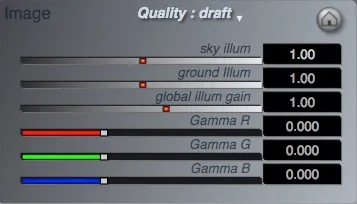
The Image Settings area collects all controls that globally affect the rendering: the quality setting, various illumination gains and the gamma sliders.
A Gamma filter is applied at the last stage of the rendering while the illuminations gain are taken into acount at the shading phase of various elements. Theses setting (except the quality setting), are part of the current Context variables and are thus both keyframable and can be stored in Places.
Quality Pop-up
Section titled “Quality Pop-up”Options: Draft, Good, Better, Best, Sublime
This pop-up menu determines render quality (of both the image on the canvas and any pictures or movies rendered to disk).
Higher quality settings involve more computation resources that Voyager must perform in order to calculate the image and the longer it takes for Voyager to render the image. In some cases you may encounter strange artifacts at the lower quality settings due to insufficient sampling steps in particular for terrains with steep peaks or tiny features (a tiny steep spike can fall in-between samples and be missed). A higher quality setting will increase the amount of samples and will make features misses less likely. When performing draft renders, you may want to use the lowest quality that provides acceptable results. For final animation rendering, it is recommended that you use Better or Best quality as misses can cause flickering where fine details occur and make small peaks appear and disappear unnaturally.
Global Illumination Gain
Section titled “Global Illumination Gain”Global illum gain controls overall illumination gain. It is rarely needed but can be used to compensate for particular lighting conditions. High gamma values will darken the image while adding contrat so it might useful to compensate with the global illumination gain.
Ground Illumination Gain
Section titled “Ground Illumination Gain”Controls illumination gain for terrain and objects only.
Sky Illumination Gain
Section titled “Sky Illumination Gain”Controls illumination gain for sky shaders only. It mostly affects clouds and atmosphere shading. This slider is often used to enhance the clouds contrast or to make them darker if the various illuminations makes the clouds too bright.
-
RRed (Red Color Filter)
The gamma sliders use an exponential range where 0 means no change is taking place , 1 means power 16, -1 means power(1/16). Gamma values above average (0) will contrast the image.Using gamma can greatly enhance the visual impact of a rendering and may also be used to control the color balance of your image.
Note:
Voyager renders colors in 64 bits per components and the gamma and range adjustment is done before final 8-bit or 16-bit quantization allowing a much better accuracy and quality than doing these adjustments as a post process in photoshop or any graphic application.Tip:
Shift+clickthe Red gamma slider to move all the sliders together. -
GGreen (Green color filter)
Green channel of the Gamma filter -
BBlue (Blue color filter)
Blue channel of the Gamma filter
Reset color filter
Section titled “Reset color filter”
Resets color filter parameters to default (Gamma and global illum gain at 1).
Render pict to screen
Section titled “Render pict to screen”
Resets the various image controls to their defaults values.
Render animation
Section titled “Render animation”
Click the Render Animation tool render an animation. The file does not need keyframes to be animated. The clouds and waves and ripples all are automatically moved by the wind even without keyframes. Movies will take a long time to render. To stop a render, press the escape key. The duration of the complete animation is set with the Duration Tool found next to the timeline in the main window.
Mode popup (movie or picture sequence) The options are:
-
QuickTime Movie,
-
List of Pictures,
-
List of
Tiff.
The “List” options render the movie frames as sequentially numbered image files (in eitherPictorTiffformat).Such sequences are recognized by most movie editing programs. Pict/Tiff sequences are a good idea when performing a long render since nothing will be lost if the computer shuts down unexpectedly.
(movies will be unplayable if the render is interrupted).
Preset popup: The preset popup provides a list of common frame size/frame rate combinations. Choosing a preset causes the format and fps fields to be filled in with the appropriate values.
Open ArtMatic Voyager bundle
Section titled “Open ArtMatic Voyager bundle” This command is the same as
 File->Open and will prompt you to locate a Voyager bundle.
Save Voyager bundle
Section titled “Save Voyager bundle”
This command is the same as File->Save and will either directly save the cureent scene if the file already exists or prompt you to set a name to save the Voyager bundle.
Render pict to file
Section titled “Render pict to file”
Click this tool to render the scene as an image file. The Render Picture dialog opens to give you control over the image settings. You can choose dimensions up to 16000 by 8000 pixels. Renderings now always use dithering. Dithering introduces a tiny amount of color (RGB) noise to the image which greatly enhances color accuracy and avoids color-banding.
Various options are availble:
- Render Mode: Single view, stereoscopic views.
- Render: Current View, All places, All Keyframes.
Render All Places option will render a picture for each place stored in the file. Keep in mind that this can take a long time. To abort a render in progress, press the escape
ESCkey. - Anti-Aliasing:
2*2Standard (default): (4 samples per pixel).
The fastest AA mode, often insufficient for depth-field (DF) cities & textured DF objects.3*3Stronger: (9 Samples per pixel).4*4Double: (16 Samples per pixel).
Recommended to avoid flickering, in particular with DF cities and textured DF objects.- Adaptative:
Adaptive anti-aliasing oversampling is applied only when fast changes in depth and color occurs which makes it faster than a bruteN*Noversampling. For terrains it works only when the camera is set to perspective and spherical due to specific optimisation in the cylindric case. Its speed is quite variable depending on the scene, but it is often better and faster than the4*4oversampling.
ArtMatic Voyager Preferences :
Section titled “ArtMatic Voyager Preferences :”Aspect Ratio
Section titled “Aspect Ratio”Sets the overall aspect ratio of the canvas.
- Square
- 4:3 Horizontal 4 by 3 ratio.
- 16:9 The HD aspect ratio, most commonly used for animation.
- 16:8 This
2:1ratio is suited for 360 degree environment map creation.
Resizing pop up
Section titled “Resizing pop up”- Keep width
When rendering at a different ratio than the overall aspect ratio this choice will keep thexrange. - Keep height
When rendering at a different ratio than the overall aspect ratio this choice will keep theyrange.
Window Skin
Section titled “Window Skin”Sets the UI skin style:
- Blue Steel,
- Metal Noise 45,
- Dark Noise,
- Shaded Metal,
- Shaded Grays
- Paper Blueprint
Snap to ground using the map (checkbox)
Section titled “Snap to ground using the map (checkbox)”When clicked ON click on the main ui Map area will land the camera close to ground level automatically.
Open last at launch
Section titled “Open last at launch”(checkbox 1.5 addition)
When ON this checkbox option will make Designer start with the last opened Voyager file to save time when working on a project. Turn it off if you want to start with a new scene. Note that Voyager will use the last context variables and terrains anyway.
Map mode
Section titled “Map mode”Map mode provides 2 ways of drawing the top view map:
- Bump & texture shaded: Use the terrain texture with bump shading (default)
- Elevation color map: Maps the elevation to the color palet provided below.
Choose gradient
Section titled “Choose gradient”
edit gradient
Section titled “edit gradient”
Calls the gradient editor to modify the elevation color palet
Balance light energy (checkbox 1.5 addition)
Section titled “Balance light energy (checkbox 1.5 addition)”When ON Voyager will use a new illumination model developped for CTX 1.5 that normalizes the coefficients of all type of light transport mechanism so that the sum of all stays below 1.
Practically it means that all levels are balanced automatically so that light output can’t be bigger than the inputs which was a problem before with reflections for example. So high reflections will lower diffuse, specular and ambiant internally.
With “Balance light energy” ON it is easier to obtain a more pleasing and realistic illumination. Examples are provided in /Voyager Examples/VY15 Examples/Illumination/
Reference Fps
Section titled “Reference Fps”Provides the default fps (frames per seconds) for animation.
High Freq limit
Section titled “High Freq limit”This setting adjusts the high frequency filtering limit. Keep it at 100% to have the maximum details. If too much flickering occurs when animating you may try to lower it to 70% or less.
Distance of horizon
Section titled “Distance of horizon”(Kilometres) The maximum distance of visible objects and terrain can be adjusted here. (Usually at 120 km).
Ambient Occlusion Radius (meters)
Section titled “Ambient Occlusion Radius (meters)”Sets the average Ambient occlusion radius for objects.
Fractal object detail
Section titled “Fractal object detail”This setting can lower the high frequency limit of fractal DF objects. Keep it at 100% to have the maximum details. If the fractal looks to noisy you may try to lower this value.
Sprite inspector
Section titled “Sprite inspector”There are 32 available slot for sprites images or sprite artmatic system. Click open in the first empty slot to add a new one. The Voyager Library/2D Sprites/ folder contains many sprites presets and examples, including a collection of people png.
Map view
Section titled “Map view”You can place sprites on the map directly by clicking on it. This set the object x, z position in world space. To adjust the sprites altitude use the y position slider in main ui and make sure the selected object is the target of the slider. All sprites position are drawn on the map using a cross surrounded by a disc. A green cross indicates the selected one.
Center Map to eye
Section titled “Center Map to eye” Center the map view to the camera eye position.
Center sprite to current view
Section titled “Center sprite to current view” Use this button to place the selected sprite in the center of the current view. If the sprite is not hidden by another object it should appear in the camera preview image.
Center Map to sprite
Section titled “Center Map to sprite”
Center the map view around the current selected sprite position in world space.
Land sprite
Section titled “Land sprite”
Use this button to land the selected sprite to the ground. This will place the bottom of the sprite at the current ground level. When the sprite is an unbounded artmatic system this places the center to the ground.
Offset Map view
Section titled “Offset Map view”
Use this button to adjust the map view location
Map Scale (radius) in km
Section titled “Map Scale (radius) in km”
Use this button to adjust the map view radius
Sprite height (meters)
Section titled “Sprite height (meters)”This field set the sprite size. By default it is set at 1.9 meters. Depending on the scene this may be too small to see and true dimensions sometimes are not necessary so you may need to adjust it to unrealistic values.
Replace sprite…
Section titled “Replace sprite…”
Replace the sprite wwith another file.
Reload sprite
Section titled “Reload sprite”
Reload the sprite file from disc.
Edit ArtMatic system
Section titled “Edit ArtMatic system”
When the sprite is a 2D artmatic system you can open it in ArtMatic Designer with this button. There is no specific editor for png sprites and you can use your favorite image editor application outside Voyager.
Sets the rendering mode for the sprite. ArtMatic 2D systems : Usually the alpha output of an RGBA system provides the basic opacity. For scalar systems, the output value is treated as an alpha channel that sets the object’s basic opacity. Sprite light objects are blended with the Voyager scene using an additive transfer mode and the alpha channel is ignored. Use additive mode for light or special illumination effects like flares or halos.
Sprite rotation
Section titled “Sprite rotation”Sets the sprite orientation when “Always face eye” is OFF
Always face eye (checkbox)
Section titled “Always face eye (checkbox)”When active this make the sprite always face the camera. Since the sprite is a flat 2D image this is often required.
Clear reference
Section titled “Clear reference”
Delete all references to the selected sprite from the scene. This will also remove the file from the VY bundle so use it with caution.
Ambient level
Section titled “Ambient level”How much the sprite will respond to ambiant colors.
Self Illumination level
Section titled “Self Illumination level”Turn this high if you need the sprite to be self illuminated, that is to be shaded independently of the sun or scene lights.
Specular level
Section titled “Specular level”- MFD roughness
- MFD shininess
- MFD hilights spread
Sets the material properties of the sprite.
Max dist for shadows (meters)
Section titled “Max dist for shadows (meters)”You can turn off shadows for a sprite setting this field to zero.
Shadow Softness %
Section titled “Shadow Softness %”Mainly for sprite png, this blurs the sprite shadow map.
Specular Color
Section titled “Specular Color”The Specular color will filter the specular reflections at certain angles.
Reflection Color
Section titled “Reflection Color”The Reflection color will filter the mirror reflections if any. The amount of true reflection is set with this color alpha channel.
DF Objects inspector
Section titled “DF Objects inspector”ArtMatic Voyager can use certain ArtMatic systems to create fully-3D objects via a technology called Distance Field Ray Marching or DFRM, for short. Only ArtMatic systems that make use of the X, Y and Z global inputs can be used for 3D objects. The output should be scalar (one-output component) or RGBA with A storing the distance field.
There are some special requirements for ArtMatic systems to be rendered correctly as 3D objects covered in greater detail in the Building Objects. In short, DFRM generally requires that the ArtMatic system be based on its special 3D-object DF components (which technically-speaking are Density Estimate Fields). DFRM can even be used to create 3D from 2D images as an elevation map can displace a DE field.
DFRM objects can be designed to be influenced by the Voyager elevation. The objects can be free-standing, floating objects or integral to the landscape. They can be infinite and planet wide like a full DF city or be local like a simple DF sphere.
You can create entire DF based landscapes for true volumetric terrains that can have overhangs, caverns and floating rocks. By using the No Planet Surface mode, you can use DF objects to create nonlandscape 3D images like floating asteroids in space. Furthermore 3D objects rendering can make full use of the ArtMatic Extra Outputs settings to modulate shading variables.
Map view
Section titled “Map view”You can place objects on the map directly by clicking on it. This set the object x z position in world space. To adjust the object altitude use the y position slider in main ui and make sure the selected object is the target of the slider.
The map view functions much like the surface overview in the main user interface. The orange lines indicate the current field of view. The blue line indicates the direction in which the camera is pointing. A blue circle indicates an ArtMatic DF object. The current selected object is marked with a green x. You can select another object by clicking on the object name list in the bottom of the window.
Note that objects positions are global and are shared between places and keyframes. Clicking in the overview, places the current object where you click. Click and drag on the Map Scale button (+-) to zoom the overview in or out.
Center Map to eye
Section titled “Center Map to eye”
Centers the map view to the camera eye position.
Center object to current view
Section titled “Center object to current view”
Use this button to place the selected object in the center of the current view. If the object is not hidden by another object it should appear in the camera preview image.
Center Map to object
Section titled “Center Map to object”
Center the map view around the current selected object position in world space.
Offset Map view
Section titled “Offset Map view”
Use this button to adjust the map view location
Map Scale (radius) in km 0.196
Section titled “Map Scale (radius) in km 0.196”
Use this button to adjust the map view radius
Land Object
Section titled “Land Object”
Use this button to land the selected object to the ground. This will place the zero of the object at the current ground level.
Open ArtMatic system
Section titled “Open ArtMatic system”
Load another ArtMatic system to define the current object. The ArtMatic system scalar output or Alpha output needs to be a true 3D DE field (Distance Estimate Field or DF in short).
Reload ArtMatic system
Section titled “Reload ArtMatic system”
Reload the ArtMatic system from disk. This can be useful if the system was modified without Voyager being notified.
Edit ArtMatic system
Section titled “Edit ArtMatic system”
Open the current object in ArtMatic for further editing. ArtMatic engine versions should match. If you have several ArtMatic versions make sure to launch the correct one before using this button.
Clear reference
Section titled “Clear reference”
This button permanently clears the file and the reference to a particular object. Use it only when sure that you want to dismiss it. You can temporarily remove an object from the scene using the Active checkbox without deleting the file.
Active (checkbox)
Section titled “Active (checkbox)”Activate or deactivate the given object. Unactive object won’t show in the scene.
Object Scale %
Section titled “Object Scale %”Set the object overall scale in percent.
Send Terrain Elevation
Section titled “Send Terrain Elevation”(checkbox)
For the true 3D objects, Send Terrain Elevation is an available option that allows the ArtMatic system to receive terrain elevation information via global input A2. This option is useful for allowing elevation to influence objects. For example, you can add this value to the global Y input to have jittered objects or grass follow the planet’s terrain. Or you can use it to allow the terrain elevation to influence the object’s color or position. The elevation information is filtered to avoid having small terrain details unduly influence the objects.
HF filter
Section titled “HF filter”When Send Terrain Elevation is ON the HF filter slider alows to filter out high frequencies.
Specular color, Reflection color
Section titled “Specular color, Reflection color”Specular Color and Reflection Color determine the object’s sheen and reflectivity. Specular Color provides diffuse reflected light and controls what you might call sheen or gloss. Reflection Color provides accurate directional reflections.
Specular Color and Reflection Color have a color picker to choose the color of the reflections and an amount adjustment. Drag up/down on the amount adjustment to adjust the amount. The amount is displayed as a grayscale shade where black is 0 and white is maximum. Direct reflections which are controlled by Reflection Color alpha/amount are processor-intensive since they are exact reflections of the entire scene. Depending on the object material properties and the incidence angle reflected light may be colored more or less by the reflection color. In Voyager 1.5 CTX the maximum colorization occurs when object is very rough. Very shining object will reflect light without coloring it. Intermediary materials will color the reflected light more when the angle between the view vector and the normal is low (Normal is facing the view vector).
Shading
Section titled “Shading”This pop up sets the shading/rendering algorithm for the current object. For a deeper discussion see Building Objects: Shading DF Objects. The Options pop up below sets the shading/rendering options for the current shading algorithm if any.
Volumetric opaque:
Section titled “Volumetric opaque:”This mode renders a solid 3D object and is useful for a mindboggling variety of surface-shaded opaque volumes, from plants to space ships, houses to entire cities. If the ArtMatic system has only a single output value, the output defines the object’s shape, and the color is white (but the apparent color can be changed using the object’s specular/reflection properties). If the ArtMatic system provides RGBA output, the alpha channel defines the object’s shape and the RGB outputs provide the object’s colors. ArtMatic Extra Outputs (X Outs) can further modulate shading variables like reflectivity or ambiant level if they are assigned in the ArtMatic params & shaders inspector.
Volumetric lights:
Section titled “Volumetric lights:”In this mode voyager accumulates volumetric light density to create a host of effects: fire, smoke, light rays, bio luminescent creatures, and many special effects.
Positive regions of the DE field serve as density values while negatives works as usual as distance estimation. The occlusion slider determines how much light from the background is occluded by the light DF object. The light density slider adjust the intensity of the DE field interpreted as light. The correct light density values are strongly dependent of the shading option and the maths of the DE field. Good settings for one shading option won’t work with another.
Usually he light direction is derived from the normal of the DF unless you use the “Projector mode”. Since the DF normal derived direction is not always physically meaningfull shadows are disabled unless you provide an extra light direction output in the ArtMatic system that you will assign to “light direction” in the ArtMatic params & shaders inspector. Options picker for Volumetric lights :
- Square fallout:
The light direction is taken from the normal of the DF field. The light itself is shaded with a square fallout (light decrease a the square of the distance). - Projector mode:
The object center becomes the source of light and gives the light direction. The light itself is shaded softly so you can simulate projectors beams for example. - Atmospheric halo:
The light direction is taken from the normal of the DF field. The light itself is shaded with more halo - 1/dist fallout:
The light direction is taken from the normal of the DF field. The light itself is shaded with 1/ distance fallout.
Examples are provided in: /Voyager Examples/Shading & Rendering/DF lights fields/
Jitter opaque:
Section titled “Jitter opaque:”Jitter opaque is a variation of the volumetric opaque mode used to replicate an object throughout an environment with small variations so that the repetitions are not identical. Voyager essentially breaks up the environment into randomized cells and instantiates one copy of the object into each cell with a ‘jittered’ (randomized) center and rotation. ArtMatic global A3 is sent a unique randomized value for each cell that can be used to randomize the object properties. You can use this technique to create an entire forest from a single tree.
Opaque & Translucent:
Section titled “Opaque & Translucent:”This mode renders a solid 3D object like Volumetric opaque but adds some light through diffusion within the medium. It is suited for leaves or surfaces that can have some light go through. The “light transmission” and “light transmission range” parameters controls how much and how deep light can travel trough the medium. Light travelling inside the medium is colored by the reflection color and the object texture color.
Fractal opaque:
Section titled “Fractal opaque:”Fractal opaque render opaque solid 3D object like volumetric opaque but “thicken” the DE field. It is suited for infinitely thin 3D fractal sets that would look too noisy or disappear in Volumetric opaque mode.
Transparent (surface):
Section titled “Transparent (surface):”Use this mode to render transparent 3D object without light refraction. It is faster than Transmissive as no additional rays have to be casted.
“Opacity gain” sets the amount of transparency. At 1 the object is opaque.
Transmissive (surface):
Section titled “Transmissive (surface):”Transmissive renders transparent 3D object with light refraction like glass, water or jelly but treat the object as surface-only.
The Options picker for Transmissive shader basically sets the index of refraction of light when passing from air to the given medium. The rays are deviated accordingly. The deviation is minimal for Helium and maximal for Diamond.
The MR set fires multiple rays while the 1 Ray set fires only the first ray through the surface at closest intersection. Examples are provided in /Voyager Examples/Shading & Rendering/DF Special Shaders/
Transmissive (volumetric):
Section titled “Transmissive (volumetric):”This mode renders transparent 3D object with light refraction like glass or water and can take into account volumetric density interior.
The Options picker for Transmissive shader basically sets the index of refraction of light when passing from air to the given medium. The (1R, shaded) or (MR, shaded) sets use a volumetric accumulation rendering for the object interior to filter the light going through the medium.
Examples are provided in /Voyager Examples/Shading & Rendering/DF Special Shaders/
Fuzzy loose:
Section titled “Fuzzy loose:”Volumetric accumulation rendering.
Fuzzy:
Section titled “Fuzzy:”Volumetric accumulation rendering. Only the volumetric interior is rendered and shaded by accumulation and there is no surface shading. Specular is off in this case. ‘Fuzzy’ shading mode can be used for fuzzy objects an even plants.
Gas & Clouds:
Section titled “Gas & Clouds:”In this mode DF object are rendered as clouds to provides a more flexible solution for certain types of clouds and smoke-like objects than the normal sky/cloud method. You can use this mode for making smoke, steam, fog, clouds and even impressionistic vegetation seen from afar.
This mode’s parameters are:
- Opacity gain: the gaz opacity gain
- Self shadow distance: The length of the self-shadow accumulation ray
- Self shadow gain: The strength of the self shadow
- Derivative level: Adds fine details by applying a derivated to the DE field. This may not be realistic for gas and clouds so keep it low or zero.
- Contrast: The overall contrast
- Ambient level: Amount of light scattered from the environment
- Opaque + light: The following dual renderer are available for multi output ArtMatic systems. The second output is rendered as a DF light field.
- Opaque + Transparent: The second output is rendered as a DF transparent object.
- Opaque + Transmissive: The second output is rendered as a DF transmissive object.
Sliders:
Section titled “Sliders:”- Specular level
- MFD roughness
- MFD shininess
- MFD hiligths spread
Theses sliders defines the material properties of the object which defines how it will interact with incoming lights.
MFD (MicroFacet Distribution).
In the real world, surfaces tend not to be uniform smoothness - even surfaces that we think of as smooth, such as a billiard ball, are not uniformly smooth. Surfaces tend to have tiny microfacets, whose orientation and reflectivity determine the surface roughness and reflective properties.
ArtMatic Voyager provides some control over microfacets through the MFD (microfacets distribution) parameters in order to each different looks.There are three parameters that you can adjust that provide a broad range of surface textures:
- Roughness,
- Shininess,
- Highlight Spread.
By adjusting these three settings and the specular level, you can achieve a great many looks.
These three parameters have been abstracted to manipulate both the Fresnel curve response and microfacet distribution and they are actually driving the many internal parameters that these complex lighting models require.
For more information about microfacets and specular light, see this Wikipedia article.
Specular Level sets the overall level of the MFD specular light with respect to the diffuse light. MFD Roughness high values create rough random microfacets that transmit specular light uniformly. The surface tend to radiate light at broader angles.
Higher MFD shininess values make the surface shiny and metallic. MFD Highlight Spread. The smoother the surface (low spread and shininess values), the more that the specular light will be focused. Essentially, it controls the spreading of highlights on the surface. The interaction between this setting and the specular level and other settings is complex. When Specular Level is 0, this setting has little or no effect. When Specular Level is high, use this to accentuate specular color highlights.
Surface shade %
Section titled “Surface shade %”Available for Transmissive shaders this controls how much the surface is shaded versus the light coming trough the medium.
Tint gain
Section titled “Tint gain”Available for Transmissive shaders this controls how much the light coming trough the medium is colored by the object color.
Maximum shadow distance
Section titled “Maximum shadow distance”(meters)
You can turn off shadows for a particular object setting this field to zero. This setting allows ArtMatic Voyager to optimize shadow calculations by setting a limit distance at which the Voyager raymarcher stops scanning when calculating shadows. If the value is too low, some shadows may be cut-off.
Shadow softness %
Section titled “Shadow softness %”DF object supports fuzzy soft shadows.
Ambient level
Section titled “Ambient level”Ambient Level (range: 0 to 1) determines how much influence the Voyager environment has on the object’s color. When Ambient Level is 0, the object’s color is not influenced by the colors in the Voyager scene. When Ambient Level is high, one can see the influence of the Sky color on the object. Now the exact color of the ambiant light depends also on the environmental ambiant mode preference. In Voyager 1.5 it is possible to force the ambiant light to a constant white.
Light emission range
Section titled “Light emission range”(meters)
Available for light field object this sets the range of illumination by the field.
Ambient Occlusion
Section titled “Ambient Occlusion”The type of Ambient occlusion is chosen with the following picker:
- None: No AO is computed.
- Terrain only: Object AO is added only to the scene terrain.
- Terrain & Self: Object AO is added to the scene terrain and to itself.
- Everywhere: Object AO is added to everywhere, the scene terrain and to itself and to other objects.
- Everywhere + LowFreq AO: Object AO is added to everywhere using a slower low frequency ambient occlusion.
- Everywhere + Edges backlight: Object AO is added to everywhere with a special backlight shading on object edges.
The slider below sets the amount of Ambient occlusion.
Lights inspector
Section titled “Lights inspector”The Lights inspector gather all tools to setup and shade built-in additional lights. Lights positions and settings are context-dependent so places and keyframes can have different lights. Keep in mind that when you edit light you edit the current context lights.
All your work may disappear if you select another Place, keyframe or simply launch a keyframed animation because the keyframed (or place) context will replace the current context. Make sure to save a place with the new lights setting and if you are working on an animation to resave a particular keyframe or use the Copy to all keyframes button.
Map view: Click to place object
Section titled “Map view: Click to place object”You can place lights on the map directly by clicking on it. This set the light x z with default y. To adjust the light altitude use the light y position slider in main ui. The inspector does not prevent using main ui sliders and tools.
Center Map to eye
Section titled “Center Map to eye”
Center the map view to the camera eye position.
Center object to current view
Section titled “Center object to current view”
Use this button to place the selected light in the center of the current view. If the light is visible and not hidden by another object it should appear in the camera preview image.
Center Map to object
Section titled “Center Map to object”
Center the map view around the current light position in world space.
Offset Map view
Section titled “Offset Map view”
Use this button to adjust the map view location
Map Scale (radius) in km 0.196
Section titled “Map Scale (radius) in km 0.196”
Use this button to adjust the map view radius
Land object
Section titled “Land object”
Use this button to land the selected light to the ground.
Active (checkbox)
Section titled “Active (checkbox)”Activate or deactivate the given light. Unactive object won’t show in the scene.
Type of light picker
Section titled “Type of light picker”- Point light: Simple point light. The light radiates in every direction and falls off progressively according to “Attenuation dist” parameter.
- Additional Star: The light is treated as an infinite light source (parallel rays because the source is very far) like an additional sun and is shaded in the sky dome when visible. Out of this world landscapes can be created with planets having 2 or more suns.
- Directional beam: A simple point light with a directional radiation. The light radiates in the direction set by the light ball controller and falls off progressively according to “Attenuation dist” parameter.
Size when visible %
Section titled “Size when visible %”When light is visible and shaded this sets the size of the light sprite rendering. Note that the light halo is a 2D sprite and may not interact with 3D object correctly unless adjusted to avoid intersections. If you need a real volumetric light halo its possible using DF lights.
Attenuation dist (meters)
Section titled “Attenuation dist (meters)”Adjust the distance where the light has any effects.
Light ball controller
Section titled “Light ball controller” Like the main sun controller this tool sets the light direction for directional lights sources.
Light color box
Section titled “Light color box”Click here to set the light color.
Intensity
Section titled “Intensity”Use this slider to adjust light intensity
Copy to all places
Section titled “Copy to all places”Lights positions and settings are context-dependent so places and keyframes can have different lights. To force lights to be the same in all saved places use this button.
Copy to all keyframes
Section titled “Copy to all keyframes”Lights positions and settings are context-dependent so places and keyframes can have different lights. To force lights to be the same in all keyframes use this button. You may also disable light animation of position in the Animation dialog.