
ArtMatic Designer Manual
ArtMatic Designer Creative ToolboX Overview
Section titled “ArtMatic Designer Creative ToolboX Overview”by Eric Wenger
- Overview & Basic Concepts
- Preferences
- Canvas View, Main Gradient and View tools
- Global Input Matrix
- Tree Editing & Shading area
- Parameter area
- Mutations Explorer Dialog
- Timeline and Keyframes Area
- Left Tool buttons
- Component Descriptions
- Video Tutorials on YouTube
Overview & basic concepts
Section titled “Overview & basic concepts”ArtMatic is a unique kind of software: it can be seen as a resolution-independent modular graphics synthesizer, as well as a mathematical visual programming engine. In ArtMatic you don’t create an image. You design the rules or algorithm that creates images. In a sense ArtMatic is a development environment, a huge toolbox of over two thousand functions you can assemble in infinite ways.
ArtMatic’s unique user interface allows you to interact with it in a variety of manners. You can create trees from scratch, tweak and mutate any of the provided presets and examples, or discover and explore entirely new image spaces with ArtMatic’s powerful randomization and mutation tools. ArtMatic Designer is primarily conceived for creating images and animation. With its enormous set of components you can:
- Create natural-looking textures and decorative patterns of all kinds,
- Create and explore beautiful 2D and 3D fractals,
- Create procedural terrains for ArtMatic Voyager or 3D applications,
- Create 3D DF objects for ArtMatic Voyager,
- Create density functions for volumetric clouds for ArtMatic Voyager,
- Create modular sound synthesizers to produce a rich variety of sounds much-appreciated by sound designers and electronic music composers,
- Explore and shade mathematical systems of all kinds. With its extensive set of mathematical tools, ArtMatic offers a fun way to explore, teach and visualize mathematics.
Keep in mind ArtMatic Designer is an open system. There is in fact no limit to what it can be used for. With a Compiled Tree you can design your own custom functions that will further enrich the huge toolbox of the ArtMatic Engine. ArtMatic Designer rendering is limited to 2D. Its companion ArtMatic Voyager is designed for 3D rendering of terrains, clouds and 3D objects created in ArtMatic Designer.
Structure Tree & Components
Section titled “Structure Tree & Components”The structure tree is a web of components wired together in limitless combinations. It is essentially a flow chart that defines the procedural mathematics creating the image. The tree takes its initial inputs from image space coordinates, time and various optional global inputs. Values flow from top to bottom and are transformed by each component until the bottom component(s) output the final results.
Each component has up to four parameters that can be modified over time using keyframes. Components are represented graphically by a Tile. The term Tile is often used in place of Component. Components can have 1 to 4 input dimensions and 1 to 5 outputs. When a final Tree component outputs a single value, the tree can be seen mathematically as a scalar 2D or 3D function. When the final Tree component outputs an RGBA vector, the entire tree is an image rendering algorithm that creates each pixel color and alpha value. The number of input dimensions used by the Structure Tree determines if the system is 2D, 3D, or even 4D (if the Tree uses global time input as well.)
The number of inputs of a component sets its dimension, the number of outputs sets its type - scalar or vector (2D to 5D). Components are often referred to by using the in-out number before the component’s name, so that the component’s type and dimension are clear.
For example:
3:1perlin noise will refer to a 3D scalar noise function that has 3 inputs (3D) and 1 output (scalar).
A number of components allow you to access and process external images and movies (up to eight different movies or pictures can be accessed in a single tree.) These components are especially powerful for creating video special effects. Complex fades and wipes and sophisticated distortion and color-processing can all be animated and rendered as movies or image lists.
Components are described individually in the reference files below, organized by input/output dimensions. A particular component’s reference can be invoked from ArtMatic Designer with command+F (Online Help Menu) after selecting a Tile. The aim of a full interactive reference system accessible online is to provide an accurate and scientific database of what each component does to make ArtMatic’s huge toolbox a seriously documented toolset, usable not only in computer graphics but also for education in mathematics and computer science.
A structure tree can hold other structure trees in the form of Compiled Trees. This makes highly complex and rich systems with hundreds of components possible, and easier to manage.
Parameter space
Section titled “Parameter space”A structure tree defines a mathematical system that can have many states depending on all the components’ parameter settings.
The ensemble of parameter values in a tree is sometimes referred to as the parameter space. A point in the parameter space is a set of all particular parameter values at that point. ArtMatic “parameter space” dimensions can be huge, often over a hundred dimensions. Keyframes store a particular point in that space. Changing parameters moves the system to another point in parameter space and animation can be seen as a trajectory in the parameter space between keyframe points.
Not all points in this giant space give interesting results, but ArtMatic was designed to provide many ways to explore this space and find interesting places, such as randomization, keyframe interpolation and the Mutation dialog.
Resolution and outputs
Section titled “Resolution and outputs”ArtMatic’s resolution is nearly infinite, both in depth and range. By default, the canvas view is centered around zero and has a radius of Pi (Π). Moving the virtual camera or zooming it in or out can often reveal vastly different images from the same Tree. As a mathematical procedural function a Tree is resolution-independent. Some fractal functions are nearly infinite in depth so you may zoom by several orders of magnitude and still find details. The large set of procedural patterns and noise functions provided by the ArtMatic Engine are only limited in extension by the range of what is representable in a 64-bit floating point system, which is huge. Thus you can have a terrain that spans an entire planet surface of 30,000 km2.
By default ArtMatic Designer shades 1D output Trees with the current Gradient by implicitly mapping the output values to the current gradient. Trees with 2 outputs are shaded likewise but both output gradients are blended into a single color. Trees with 3 outputs are interpreted as an RGB Tree and the resulting color is taken directly from the RGB value. Trees with 4 output tiles are interpreted as RGBA with the fourth output setting the transparency or Alpha channel. Negative and zero values are treated as transparent.
ArtMatic Tree systems that output RGBA can be rendered as PNG or TIFF images that include an Alpha channel. PNG images can be rendered in 16-bit per channel allowing the maximum quality. Scalar Tree systems (a single-valued output) are usually rendered using specific shaders that map the output to RGB and will be rendered without an alpha channel as RGB tree systems.
The number of output tiles is not limited to 1. ArtMatic Voyager makes use of multi-output trees for various shading needs as documented for example in Shading DF Objects/Using extra outputs. ArtMatic Designer can also render Multi outputs systems in the RGB Multi mode or by using various shading options like depth Cueing.
Definitions
Section titled “Definitions”-
ArtMatic Engine: Refers to the toolbox and rendering engine that is shared by
ArtMatic Designer,ArtMatic Voyager,V-Quartzand future apps that will benefit from the same engine. -
Structure Tree: The ArtMatic Structure Tree, often called an ArtMatic system, is basically the set of Components connected together that define the procedural function described in Structure Tree & Components. An ArtMatic file is composed of its Structure Tree plus additional shading variables and optional gradient data.
Structure Tree design and editing is only available with ArtMatic Designer in the Design Room. Most of the time you will modify existing trees by changing their components and eventually adding new functions. Advanced users may want to create complete trees from scratch. All the tree building and editing tools needed for that are found in the Tree Editing & Shading Area. Learn more about designing tree concepts in the Building trees page.
-
Compiled Tree: A Compiled Tree (CT for short) packs a Structure Tree in a single Component. With CTs, Structure Trees can be nested without any limit in levels (CTs can contain CTs that contain CTs). A single level can contain several CTs so there is no limit in the complexity of an ArtMatic Structure Tree. In general, Compiled Trees that have the same number of inputs as outputs can be used in feedback mode for recursive computation. Compiled Trees for each Component type are described in more detail in the component references organized by input/output dimensions. For example 2:1 Compiled Tree will discuss 2D scalar CTs, while 3:3 Compiled Tree will discuss 3D vector CTs.
-
Streams: A stream simply refers to the flow of data through a set of components. An
RGB streamrefers to the series of components through which RGB or 3D vector data are flowing. RGBA streams are 4D vector data (that can be packed or not) and represent a color + alpha. -
Band-limited. A function is band-limited when its frequency content falls within specific intervals. You can think of frequency as a measure of the size of the function’s features — high frequencies generate small-scale features and low frequencies generate large-scale features. The Perlin Noise function is a good example of a band-limited function whose output falls in a very narrow frequency band.
-
Continuity. A function is said to be continuous when its derivative (its local slope) does not exhibit any sudden changes. Continuity is an important issue for ArtMatic Voyager. Certain functions (such as the Step Quantize function) produce a non-derivable, non-continuous result. Many discontinuous functions have a “smooth” variant, or a smoothing parameter that softens the discontinuity and makes the result continuous.
-
Linearity. A function is said to be linear when its derivative (or slope) has a constant value. If you connect the derivative operator to a linear function (such as the plane Ax + By + C component), you will just obtain a single color - an expensive way to clear your canvas!
-
Multi-fractal. A multi-fractal function is a function with a varying fractal dimension. Fractal dimension is a measure of statistical roughness. Multi-fractals are very good for capturing the complexity of natural textures.
-
Periodicity. A function is said to be periodic when it repeats itself ad infinitum with a specific period.
ArtMatic Designer User Interface
Section titled “ArtMatic Designer User Interface”Interface Basics & Conventions
Section titled “Interface Basics & Conventions”Almost everything that you can see in the user interface is active, including the text, icons and glyphs. Pretty much every graphic item can be clicked or dragged to perform a task. Like all U&I Software applications, most tools are accessible directly from the user interface.
- Tool-Tips: The Tool-Tips area found at the bottom-center of the main window provides contextual information about whatever is under the mouse. Move the mouse over any user interface item to display helpful information. Often the tip will include shortcut keys if any.
- Numerical controls and sliders:
Numeric controls allow you to change values by typing or by clicking and dragging. When typing, complete the entry by pressing return or the enter key. Selecting another field should also validate the entry. You can change the number with smaller increments by pressing the
optionkey while dragging a slider horizontally or a number field vertically. Vertical dragging from the number allows greater accuracy than the sliders as the range is not limited by the scroller dimension and is about 500 pixels. - Shortcuts:
*(times 2) changes the field value to twice its value/(divide by 2) changes the field value to half its valuei(invert) changes the field value to 1/value,d(degrees) interprets the entry as degrees converted to radians and shall be used at the end of keyboard entry. For example, to get exactly Pi, type 180 thend. d should validate the entry automatically.optionkey: All numeric fields and sliders are sensitive to the option key to increase precision by 50x. If the shift key is pressed along with the option key, the accuracy is augmented by 500x.
- Color Pickers:
Color swatches allow you to change various colors. Click and hold a swatch to pop up the color picker. The cursor becomes an eyedropper that picks up the color beneath it when the mouse is released, which makes it easy to grab color from anywhere in the background.
Unfortunately, in recent MacOS versions, Apple has made the reading of screen pixels subject to authorization, so you will need to grant ArtMatic the right to access the screen; otherwise, the color picker won’t work. Keep in mind the picker can read any color anywhere on the screen, which is extremely useful. For example, you can pick any color from a picture unrelated to Voyager on the desktop.
Preferences (ArtMatic Designer)
Section titled “Preferences (ArtMatic Designer)”Aspect Ratio
Section titled “Aspect Ratio”Sets the overall aspect ratio of the canvas. The 16:8 (or 2:1) ratio is handy to build and visualize 360° environment maps or when using the Voyager 3D Sky Dome Global Input Matrix mode.
- Square
- 4:3
- Horizontal 3:4
- 16:9 - The HD aspect ratio, most commonly used for animation.
- 16:8 - This 2:1 ratio is suited for 360 degree environment map creation.
- 3:4 - Vertical 3:4, added in July 2020 builds.
Maximum iterations for fractals
Section titled “Maximum iterations for fractals”Determines the number of iterations used by fractal noises and certain iterative functions. The larger the value, the higher the resolution of these functions when zoomed in, as iterations add higher frequencies most of the time. With large values images may take longer to calculate. Setting this value high will produce more upper harmonics that let you zoom far inside the fractal to discover lovely details found at the “microscopic” level. This also affects the level of detail within ArtMatic-based terrains used in ArtMatic Voyager.
Automatic high res render
Section titled “Automatic high res render”When ON this checkbox option will trigger an anti-aliased rendering after any changes in the ArtMatic Trees or its parameters. This is generally unneeded as it slows down the workflow and a hi-res render can always be done at will using the render hi-res eye icon below the canvas view.
Preview Resolution
Section titled “Preview Resolution”Preview resolution sets the pixel size resolution of preview rendering and fullscreen animation playback. In the main UI, the animation playback uses an adaptive resolution and this number sets the lowest possible pixel size.
Window Skin
Section titled “Window Skin”Sets the skin of the ui among:
Blue Steel,
Metal Noise 45,
Dark Noise,
Shaded Metal,
Shaded Grays
Paper Blueprint
- Tuning Key: Sets the tuning key reference. (A0 = 0, A1 = 12) A sine wave at frequency 1 will use the pitch defined by tuning key reference.
- Tuning Mode: (popup) Sets the main tuning mode.
- View scaled (Pi2 based): Tuning is dependent on current canvas scaling. At default view scale, the pitch will be exactly the tuning key reference for a sine wave of frequency 1. Pitch will double when the canvas zoom doubles.
- Absolute (Pi based): Tuning is independent of current canvas scaling. This mode is safer for musical applications where the view scale shall not affect the pitch.
Random tables
Section titled “Random tables”- Random Seed The seed to generate a new random table. To change the random table, you must change the Random Seed. The same Random Seed generates the same random table.
- New Tables This button generates a new random table. A different table will change all the noises and random fractal components without changing their statistical distribution. The random table is saved in the ArtMatic file to ensure that when you re-open a file, its appearance is the same. You can change the random table by entering a new seed value then pressing the New Random Tables button.
Canvas View, Main Gradient and View tools
Section titled “Canvas View, Main Gradient and View tools”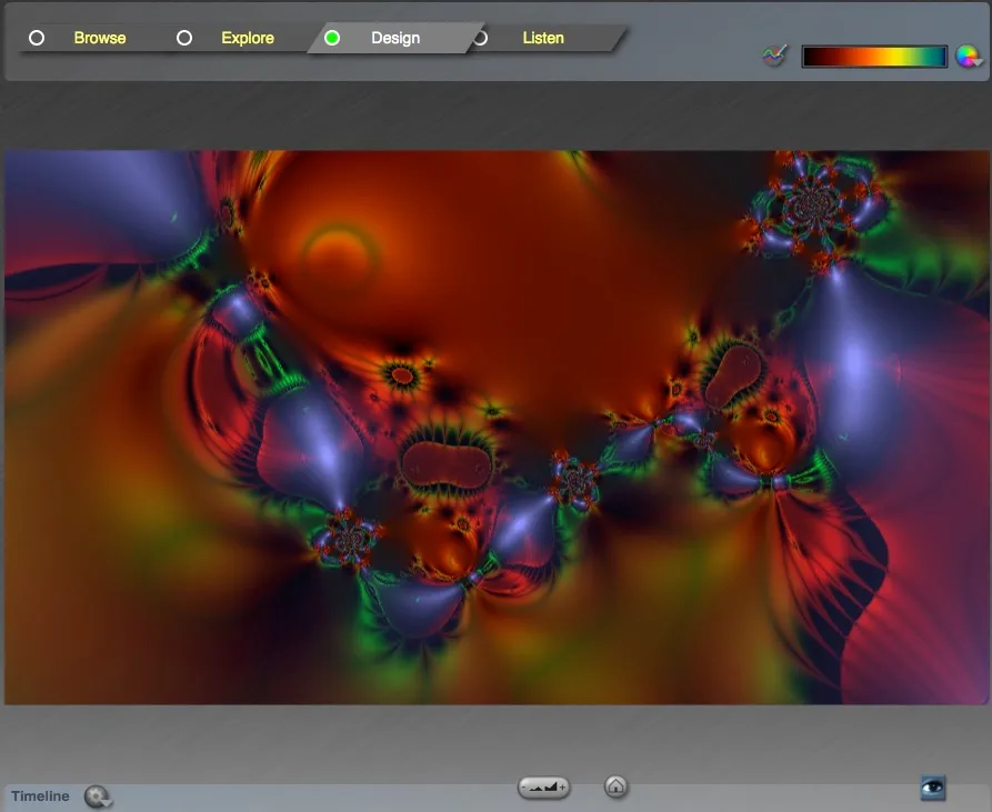
Rooms toggle
Section titled “Rooms toggle”-
Browse Room: The
browsetab provides access to ArtMatic presets created with ArtMatic Designer. By default, the folder path is set to the Libraries shipped with the software. The folder hierarchy offers thumbnail previews that allow you to select ArtMatic files in an easier way by double-clicking any thumbnail or by clicking in the larger preview. -
Explore Room:
This room allows you to play with and animate an existing system without having to handle the complexity of editing a full tree design. Up to 6 component parameters are provided in the UI for adjustments. -
Design Room:
This room provides all the tools for deep-editing an ArtMatic Structure Tree. -
Listen Room:
This room is similar to the design room, but is dedicated to sound design applications. ThePlaybutton will play the sound, and specific sound-related controls are added in the UI. ArtMatic Engine works in 44100 Hz sampling frequency only.
Main Gradient
Section titled “Main Gradient”(top right)
How the final output value is mapped to a color depends precisely on whether the tree is scalar or RGB-based. For RGB-based trees, the color is calculated directly from the 3 output values of the last Tree Tile. If the Tree is scalar or 2D (2 outputs), the color mapping is handled by the active Shading mode function, using the main gradient to provide the colors. In most cases, low values will be mapped to the left-hand color of the gradient and higher values are mapped to the colors further right.
Even when the Tree is RGB and doesn’t use the Main Gradient, it can have components that use it to shade the component results, like 1:3 Main Gradient.
What is a gradient? A gradient is a special type of palette that has a user-definable number of color stops (slots). Each stop has its own color. ArtMatic automatically generates all the colors that lie between adjacent stops by linear interpolation. With a few mouse clicks you can create rich palettes.
Each keyframe can have its own gradient. You can store your own gradients in ArtMatic’s gradient library. You can also export and import gradient libraries using the Gradient Editor.
Click on any color box of the gradient to choose another color. With
shiftkey down, the change is stored in all keyframes. Use the Edit gradient below for structural changes and more editing options.
Edit gradient
Section titled “Edit gradient”
This button opens the Gradient editor pop-up to modify the Main Gradient.
Choose gradient
Section titled “Choose gradient”
This button lets you choose the Main Gradient among the built-in list of gradients.
Canvas View
Section titled “Canvas View”You can think of the visible canvas as a downward-facing camera view of a portion of an infinite grid or plane. (This is the Cartesian plane you may remember from geometry class).
Every visible pixel is a point on the plane/grid. (Pixels are the individual dots of which a digital picture is comprised – it is an abbreviation of “picture element”.) When the canvas is in its default centered position, the center point is 0, 0; coordinate values increase to the right and up.
The Structure Tree as a whole acts as a giant equation, that takes the visible point’s coordinates as input, and generates the color used to draw the point. More simply, the Tree is just the sequence of operations that transforms the input canvas coordinates (x,y) into a final pixel color. The canvas view is then just the visible portion of the coordinates sent to the Tree for rendering the image.
To change the region of the plane/grid that is visible, click and drag the canvas left, right, up or down or use the zoom tools.
When exploring a system, it is a good idea to zoom in and out on the system, since the character of many systems varies dramatically when viewed from up close and from afar. Also, dragging the canvas left or right can reveal surprising details. The default center coordinates of a new system are 0,0 with the zoom set at 1. The x and y values range from -Π to +Π (from minus to plus Pi).
When the
shiftkey is pressed, the new view position and zoom level will be stored in all keyframes, thus suppressing any view animation.
The Animation & Camera Setup dialog displays the current zoom level and the x,y coordinates of the canvas’ center point. It can be invoked from the Animation pop up menu or by simply typing a.
Default view
Section titled “Default view”

This button resets the canvas view to the default scale (-Π,+Π) centered around zero. When the shift key is pressed, the default view scale and position will be stored in all keyframes as well.
Zoom Slider
Section titled “Zoom Slider”
Drag this button left-right to change the current canvas view zoom level. The image preview will be at lower resolution while dragging, but should redraw at normal resolution when you let go. When the shift key is pressed, the new zoom level will be stored in all keyframes as well.
Render Hi-Resolution
Section titled “Render Hi-Resolution”Keyboard Shortcut: (h)

This button triggers an anti-aliased higher resolution rendering of the current canvas view. On the left toolbar, a larger, similar icon will trigger a full screen render.
Tree Editing & Shading Area
Section titled “Tree Editing & Shading Area”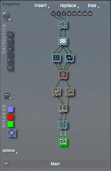
This area gathers all the tools used to edit the Structure Tree, set up Tree shading variables, and choose the global input modes. It also displays a graphic representation of the Tree (the Structure Tree View) that is fully interactive. The Structure Tree View editing area is only available in the ArtMatic Designer “Design” and “Listen” rooms.
The three pop-up menus, Insert, Replace, and Tree, provide all the tools you need for advanced and efficient Tree creation and modification. Their most useful functionality is also echoed in the Tree editing toolbar icons below the Structures presets pop-up icon. Knowing and using these menus can save you a lot of tedious work when modifying the Tree structure.
Structures presets (pop-up)
Section titled “Structures presets (pop-up)”
The Structure Presets folder provides many structural starting points for Tree building in the ArtMatic Designer Design Room. Use this pop-up to choose a new Tree structure template from the Structure Presets folder. The chosen Structure Tree will be automatically mutated. However, with the option key held, ArtMatic Designer will load the default preset file structure.
You can add your own ArtMatic files to the Structure Presets folder when they can be used as generic templates.
‘insert’ menu (pop-up)
Section titled “‘insert’ menu (pop-up)”- Insert top tile:
If a tree has parallel branches that you would like to connect at the top, choose the Insert menu’s Insert Top Tile. For 2D trees, a rotation tile is inserted at the top of the tree to which both branches are connected. You can change the component to something other than rotation if you desire. For 3D trees, a3:3space transform will be inserted at the top. Having a common father/parent tile also makes CT creation easier. - Insert perspective:
Inserts a group of tiles at the top with a perspective component by default. - Insert iteration:
Inserts an iteration tile to make the Tree iterative. A memory component is added to accumulate the results. - Disconnect:
Disconnects the selected tile from its predecessor. The selected tile (and any connected tiles after it) become a new branch of the Structure Tree. - Insert Above:
y
Inserts a component above the currently selected Tile. - Insert Below:
t
Inserts a component below the currently selected Tile. The component will have the same number of inputs as its father’s/parent’s outputs. - Insert 2 below scalar first:
Inserts two tiles below, with a scalar tile(1 out)first. - Insert 2 below scalar last:
Inserts two tiles below, with a scalar tile(1 out)last. - Append 1D filters:
f:
Appends a1:1tile to each output of the selected tile. - Append 1 out:
1
Inserts a one-output tile after the selected tile. - Append 2 out:
2
Inserts a two-output tile after the selected tile.
(Only available when the selected tile has two or more outputs.) - Append 3 out:
3
Inserts a three-output tile after the selected tile.
(Only available when the selected tile has two or more outputs.) - Append 4 out:
4
Inserts a four-output tile after the selected tile.
(Only available when the selected tile has two or more outputs.) - Add branch
b:
Adds a new branch that forks off from the selected tile. The last component in the system is modified to accommodate the new branch. - Add parallel branch:
=
Adds a new branch parallel to the selected tile. - Complete Tree:
Completes the Structure Tree by closing it and joining any loose branches. - Add Color Pict/Movie item:
Adds a color RGB Pict/Movie component after the selected tile. This command is only available when the selected tile has two outputs. - Pack Outputs:
p
Adds a pack component to the selected tile. This command is only available if the selected tile has three or four outputs.
‘Replace’ menu (pop-up)
Section titled “‘Replace’ menu (pop-up)”- Split component:
Splits the selected component into several parallel components. A
2:2tile, for example, is split into parallel1:1tiles; a three-in/two-out tile is split into a2:1and a1:1tile. This command is only active if the selected tile has two or more outlets. - Split scalar & vec: Splits the tile in two, with priority for the first tile to be scalar.
- Split vec2: Splits a 4-output tile into two 2-output tiles.
- Make group
g: Replaces the selected tile with a group of tiles equivalent to the Make Group tool. - Make z group: Adds tiles to the Structure Tree so that the selected tile feeds a three-input tile.
- Make RGBA group:
When applicable, creates a group of tiles with RGBA outputs from a selected
3:1or2:1tile. - Replace with scalar (1 out): Changes the number of the selected tile outlets to 1. (Only available if the current number of inlets is compatible with one outlet.)
- Replace with vector (2 out): Changes the number of the selected tile outlets to 2.
- Replace with vector (3 out): Changes the number of the selected tile outlets to 3.
- Replace with vector (4 out): Changes the number of the selected tile outlets to 4.
- Replace with 1 in: Changes the number of the selected tile inlets to 1.
- Replace with 2 in: Changes the number of the selected tile inlets to 2.
- Replace with 3 in: Changes the number of the selected tile inlets to 3.
- Replace with 4 in: Changes the number of the selected tile inlets to 4.
- Replace with xz transform:
Replaces a selected
3:3tile with a2:2space transform connected toxandz. This can save a lot of connecting time when you need the transform only on thexzplane. - Replace with color pict:
Replaces a selected
2:1tile with a2:3RGB Pict/Movie component.
”Tree” Pop-Up Menu
Section titled “”Tree” Pop-Up Menu”-
Copy Tile:
xEchoes the Edit menu Copy Tile. -
Paste Tile:
vEchoes the Edit menu Paste Tile. -
Delete Tile:
backspaceDeletes the selected tile. Shortcut:deletekey. -
Send Tile to Main output:
mThis command makes the selected tile the main output that calculates the image displayed in the canvas. This command is only meaningful when:- the selected tile is in the bottom row of tiles, and
- there is more than one tile in the last row.
-
Send Tile down:
oMoves a tile down one row. This only has an impact when there is space below the tile. -
Send Tile up:
uSends a tile up one level in the tree. -
Move Tile left:
<Moves the tile one space to the left in the tree. -
Move Tile right:
>Moves the tile one space to the right in the tree. -
Compact Tree:
cLets ArtMatic re-organize the tree automatically. This command is useful when you have been adding and deleting tiles and want ArtMatic to compact the display of the tree. -
New Compiled Tree:
nYou can directly create a CT from any selected tile using this command. You may also select a group of tiles for grouping in a CT using the following method:- Select the top tile as usual.
- Select the output tile using
shift+clickon a tile below. Avoid having loose branches as CTs must have a single output tile. All tiles in between should be selected. The output tile will be highlighted in pink/velvet hue. - Invoke “New Compiled Tree” to make a CT or type the
'n'key.
-
Open Compiled Tree: Opens a compiled tree into the selected tile. ArtMatic will prompt you for the compiled tree to open. Only compiled trees with the same number of inputs and outputs as the selected tile can be chosen.
-
Save Compiled Tree: Use this command to save a CT to disk for later use. It is a good idea to store useful functionality in CTs in a CT folder somewhere.
-
Edit Compiled Tree:
eEditing the selected compiled tree will open and display the CT content for editing. When editing a compiled tree, the input matrix changes to make room for CT inputs. Typeeto enter or leave this edit mode. -
Rename Compiled Tree…: Invokes the dialog to rename trees. The functionality is also available by clicking on the Tree name box.
-
Input Matrix Setup…: Invokes the Input Matrix Setup dialog that lets you set the mode described below.
Global Input Matrix
Section titled “Global Input Matrix”
The Global Input Matrix feeds information to the Structure Tree. In addition to the x and y canvas coordinates, time, audio analysis, and ArtMatic Voyager information can be sent to the tree. ArtMatic Voyager information is only sent to the tree when the ArtMatic structure is being used inside ArtMatic Voyager. The other global inputs are generally used for one of two applications:
- using time or audio input to influence the tree when rendering animation/movies,
- using information from ArtMatic Voyager to create color maps influenced by elevation and/or slope.
The information passed out of the global inputs (Z, W, A1, A2, A3, and A4) is determined by the Input Matrix mode. The x and y global inputs are always the (x,y) coordinates of the ArtMatic Canvas. The Input Matrix mode is set in the Input Matrix Setup dialog, which is invoked by clicking on any label of the Input Matrix.
-
Constant mode: Constant mode is the default mode of ArtMatic and is suited for 2D graphics and video applications.
Z: relative time normalised (Z flows from 0 to 1 during the animation span, whatever its duration. This means that the speed of Z will slow down when duration increases. Prior to ArtMatic Engine 8.0.6, the Z input was scaled by 4).W: absolute time in seconds.A1-A4: constant values.The
Zinput is time as a percentage of completion of keyframe animation. When keyframe animation plays,Zwill be0when the animation starts and1(representing 100%) when the animation reaches completion. TheWinput, which is expressed in absolute time in seconds, is useful when you want some sort of change in the animation to be unaffected by the number of keyframes or the duration of the animation. For example, if you want the canvas to rotate at a rate independent of the animation’s duration, useW. The constant valuesA1-A4that can be set in the Input Matrix Setup dialog offer an alternate way to send global values to component inputs. Unlike the1:1,1:2, or1:3constant components, the Input Matrix constant can easily be used in the tree and within several levels of Compiled Trees, with the guarantee that the values will be the same for all sub-functions, thus acting like a global. -
Audio Input mode: Use this mode when you want to animate components with audio (either from an audio file or live input) in the Design or Explore room.
Z&W: relative and absolute time;A1-A4: audio band analysis information: A1 audio bass, A2 audio medium low, A3 audio medium high, A4 audio high.For the sound analysis to affect the Tree, you will need to use values provided by inputs
A1toA4to modulate tree parameters. See the examples provided inLibraries/Master Audio Input/to learn various techniques about how to make a Tree sound sensitive. The values inA1throughA4represent the strength of the audio in each given frequency band. For example, connect a tile toA1to have the bass frequencies influence the image. The audio can come from either live audio or anAIFFaudio file. In audio input mode, the following additional parameters are available: Input Device, Input Source, Audio Sensitivity, Sound In Inertia. TheA1-A4values are created by applying eight parallel DFT filters which are summed together in pairs.A1is the sum of filters centered at 42 and 84 Hz.A2is the sum of filters centered at 168 and 336 Hz. A3 is the sum of filters centered at 672 and 1344 Hz.A4is the sum of filters centered at 7688 and 5376 Hz.ArtMatic Engine uses 44100 Hz for its sampling rate, and audio files need to be in 44.1 kHz to work properly. When connecting to an input device, make sure the device is set to 44.1 kHz sample rate. Input bit depth should not matter, as it is converted to float internally. On certain hardware, monophonic input devices seem not to be supported.
Audio Sensitivity is used to control how sensitive the system is to audio input. High values make the system more sensitive to audio. Sound In Inertia determines how smooth the transition between values is. When the inertia is low, sudden changes in the audio can cause abrupt, jittery changes. Use inertia to smooth changes caused by the audio input.
Animation playback will run forever in the main UI and Full screen preview when using Audio Input mode with live audio. To start playback and sound input capture, use the space bar. Tip! When creating systems for audio control, you may find it useful to switch the Global Input mode to constant mode. While the dialog is open, you can change the constant values and observe how the system responds to the changes. This can give you an idea of what the A1 through A4 inputs do in the system without having to play audio.
-
Time & Cycles: Time & Cycles mode is mostly used for sound design applications in the Listen room of ArtMatic Designer, but can also be handy to control various looping features independently of keyframes.
Z: absolute time in seconds. Note that z plays the role usually devoted to W input.W: integer counter (32 steps) with rate set in hertzA1-A4: free running oscillators (cycling values) set in hertz
There is an additional parameter, BPM adjust, which adjusts the speed of all the oscillators at once, allowing them all to be sped up or slowed down. The W value is an integer value that cycles from 1 to 32 at a rate determined by the frequency (in Hz) parameter. A1 through A4 are the output of four independent saw-wave oscillators. For those unsure of what an oscillator is, A1 through A4 generate floating-point values that increase steadily from 0 to 1 as time progresses and then reset to 0 and start climbing again to 1. The oscillators repeat this over and over at a speed determined by the Saw Cycle setting in the Input Matrix setup dialog. The saw waves are especially useful for creating continuous rotation when connected to the third input of the 3:2 z Rotate component.
-
ArtMatic Voyager: “ArtMatic Voyager” global input mode is used by ArtMatic files designed for 3D ArtMatic Voyager rendering. The mode provides various input information from Voyager context and rendering variables as explained below.
- Z: context dependent. When the ArtMatic Tree is
3D,zwill hold the third space coordinate. - W: absolute time in seconds.
- A1-A2: Slope & Elevation.
- A3-A4: Image space view origin
(x,y)or Image space sun position(x,y).
This information is only passed in when the ArtMatic system is accessed from within ArtMatic Voyager. When an ArtMatic file is loaded into ArtMatic Voyager, it can receive various types of information from Voyager. This is covered in greater detail in the ArtMatic Voyager documentation.
A1andA2are used to create complex color texture maps that allow color to be influenced by both elevation and slope.All values passed by Voyager through the
X,Y, andZglobal inputs are scaled according to ArtMatic’s view. The values passed throughA2are absolute and independent of the ArtMatic scale.Slope is only evaluated for color texture maps and at the color texture stage of combination-mode planets. It has no meaning when the ArtMatic structure is being used as an elevation map.
Note:
Slope and elevation are only defined when the system is being used for the color texture/shading and cannot be used by those parts of a tree that define the elevation map (since slope and elevation only make sense after the elevation map has been calculated).
In a tree that provides both color and the elevation map, the slope and Voyager elevation can only be used in the parts of the tree that define the color.
- Z: context dependent. When the ArtMatic Tree is
-
ArtMatic Voyager 3D Sky Dome:
The input mode “Voyager 3D sky dome” is suited to visualizing a 3D 360° Voyager Sky Dome in 2D or to creating 360° environment images in ArtMatic. A spherical inverse projection is used implicitly to view the Sky Dome.
X,Y, andZglobal inputs will return 3D coordinates on a sphere (with a2:1ratio). At default view size, the top and bottom lines will map to the north and south poles, and coordinates will loop inX.Using 3D for the 360 environment has the advantage over 2D spherical mapping to have no deformation near the pole and can be viewed in spherical projection from any angle within Voyager. The component 3D SkyDome Planet makes creation of planets in 3D sky dome easier. Except for the viewing geometry, this mode is equivalent to the ArtMatic Voyager input mode. A number of 3D-sky-dome based trees are provided in the Environments 360
/Voyager Library/Skies/Environments 360folder of the Voyager Library.
When editing a Compiled Tree, the Global inputs graphic makes room for slots representing the CT’s own inputs. They are labelled i1, i2, i3, and i4. You can remove one of these inputs if it is not used by option + clicking on the corresponding input circle. On some occasions, you may want to connect a Tile inside the CT to global inputs bypassing the CT inputs. For example, you may feed the CT with transformed coordinates while one element in the CT may need to use the original untransformed coordinates. In that case, you will connect that tile to the global X, Y inputs instead of i1, i2.
Structure Tree View
Section titled “Structure Tree View”There is a lot you can do by manipulating the Tree directly in the Structure Tree view area. The structure tree is the arrangement of components that generates the displayed image. Each component has a Tile that represents it and that displays the inputs/outputs and its connections with other tiles. Each tile’s outlets are fed into the inlets of the following tile. Tiles at the top are connected to the global inputs. When editing a CT, they can be connected to either the CT’s inputs or the global inputs.
To select a Tile, click on it. It should be outlined in green. Selecting a tile will update a number of associated UI items like its parameters, its algorithm, and options, if any. Once selected, you can modify all the tile’s settings by adjusting the parameter sliders in the Parameters area and various associated pop ups like main algorithm or options.
To change a tile’s function, click on any tile and hold down the mouse button to pop up a menu of the available functions. The function list varies according to the number of a tile’s inputs and outputs.
To change a tile’s input and output dimensions, control + click on any tile and hold down the mouse button to pop up a menu of the available tile’s types. By convention, the tile type names use their number of inputs and outputs as a class name. For example, a 2D surface with 2 inputs and a single output will be referred to as 2:1 'componentname'. You may also access the replace menu while clicking on a tile with the option + command keys down.
When using command + option + click on a father above, you invoke the Reconnect Dialog (see below).
Tree Connections
Section titled “Tree Connections”The connections between tiles determine how information travels through the tree. While many people stick to the preset structure trees that we provide, it is possible to create trees from scratch or modify the connections between the tiles of a preset structure. This section details a few important Structure Tree concepts and some valuable techniques for editing trees. When tiles are added or removed, ArtMatic estimates how the tile connections should be re-configured; however, there will be cases where you will need to use the Reconnect dialog to make the desired connections. The component(s) that feed the tile inputs are usually named parent(s)/father(s).
There are two ways to change the connections between a child tile and a parent tile found higher on the tree or between a tile and the input matrix:
Automatic connection command + click forces an automatic connection from a child to a parent tile. The “child” is the currently selected Tile outlined in green. When an automatic connection is made, ArtMatic will try to connect all of a tile’s inputs to the output of the parent tile. To use automatic connection, select a tile (the child) and command + click on a tile higher-up on the tree or on one of the labels of the global input matrix.
In recent software builds (> July 2020), the relative position of the new parent/father will give a hint to which inputs shall be connected by default (when parent/father output count is smaller than child’s input count). When the father is at the right, the child’s rightmost inputs will be connected instead of the leftmost, which is the usual case.
For example, if a 1 out tile carries an alpha value, place it to the right if you need the automatic connection to feed the 4th input, often the alpha value. In a similar way, if a 4-input tile mixes two 2-output tiles, place the one to be connected to 2 and 3 to the right.
The Reconnect Dialog (command + option + click) allows for custom manual connection of tile inputs and outputs. To invoke the Reconnect Dialog, select a tile and then (command + option + click) on a tile at the same or higher level. By using manual connection (with the Reconnect tile), a tile’s inputs can be fed by different parent tiles.
Using the Reconnect Dialog is mandatory when you need to change the order of connections, such as connecting x input to a z output.
Both methods require that the parent tile be higher in the tree than the child tile and can be used to either connect loose or open inputs or to change a tile’s parent. Learn more about Tree design in the Building Trees page.
Delete Tile
Section titled “Delete Tile”Key Command: backspace

Deletes the currently selected Tile. This functionality is also provided within the Tree pop-up menu. Designer attempts to reconnect parents/father(s) and children/son(s) automatically.
Note: You cannot delete the last tile, as a Tree needs at least one tile.
Insert Below
Section titled “Insert Below”Key Command: t

Inserts a component below the currently selected Tile. The component will have the same number of inputs as its parent’s/father’s outputs. The functionality is also provided within the insert pop-up menu.
When you need specific dimensions and/or specific output types, more options are available in the insert menu.
Insert Above
Section titled “Insert Above”Key Command: y

Inserts a component above the currently selected Tile. The same functionality is also provided within the insert pop-up menu.
Make group
Section titled “Make group”Key Command: g

Inserts a similar component to the right of the currently selected Tile and adds a mixing component below. The same functionality is also provided within the replace pop-up menu. This is a convenient way to make a particular feature of the tree more complex.
Add branch
Section titled “Add branch”Key Command: b

Inserts a similar component to the right and below the currently selected Tile without connecting further. This is a handy way to start a new branch. The functionality is also provided within the insert pop-up menu. An alternative way to create a new branch is to use the insert → add parallel branch function, which will add a new similar component to the right, and connect it to the same parent(s)/father(s).
Complete Tree
Section titled “Complete Tree”
The complete tree tool is provided to automatically complete incomplete trees.
In most cases, ArtMatic uses the output of a single component (the first component of the last row) to create an image. Trees should generally be complete (i.e. have only one component at the bottom of the tree with an unconnected output), except in cases where an unconnected output is used for depth cueing or global shading, or where additional outputs are used by ArtMatic Voyager. You will often find yourself needing to connect parallel branches while editing tree structures (especially if you are creating a system with several pictures or 3D objects).
When the complete tree tool is clicked, ArtMatic will mix the branches of the tree by adding and connecting the appropriate components.
For example, to mix two parallel RGB branches, ArtMatic will add any required pack components then mix the branches with a packed RGB mixer. Mixed systems that feature an RGB branch and a 1-output gradient-based branch will be mixed with the appropriate 4:3 mixing component.
Multiple 1D branches will be mixed with a two or three to one mixer. In rare cases, ArtMatic may not be able to determine how to mix the system. In this case, a beep will sound when the complete tree tool is pressed. If this happens, you will have to add some tiles yourself to complete the tree. If there is an RGB branch and a 2-output branch to mix, for instance, a 2D Scalar (2-in/1-out) component should be added at the end of the two-output branch. You can often save yourself a lot of work by using this tool.
Tree name box
Section titled “Tree name box”This box displays the names of the current Tree and subtree hierarchy. Click on the Name to rename the main Tree or the Compiled Tree if currently open for editing. This will open a dialog displaying some information about the trees and providing a text field where you can rename the Tree or Compiled Tree.
Exit Compiled Tree editing
Section titled “Exit Compiled Tree editing”Key Command: escape

Available when editing a Compiled Tree, this button will send you to the top of the tree hierarchy.
Edit Compiled Tree (e)
Section titled “Edit Compiled Tree (e)”Key Command: Select a CT tile and press e

Available when the selected Tile is a Compiled Tree, this button will open and display the CT content for further editing.
Image and Movie Inputs
Section titled “Image and Movie Inputs”Choose Pict/Movie
Section titled “Choose Pict/Movie”
Available when the Tree uses a Picture/Movie component, either black & white like 2:1 Pict/Movie or full-color like 2:4 RGBa Pict/Movie, this pop-up menu allows you to choose which picture input channel is used by the component. Choosing an empty slot prompts you to select a picture or movie that will be added as an available input source.
To further organize the inputs list, select the Setup inputs item. The invoked dialog will let you delete or add new inputs. When using movies, you will also be able to select a starting time and some playback speed options.
Movie formats:
ArtMatic Engine 8 uses Apple’s AVFoundation to display movie frames. Unfortunately, newer MacOS systems don’t support as many codecs as QuickTime did; however, most incompatible QuickTime .mov files can still be converted by QuickTime Player. You may bypass codec limitations and compression by using an image-sequence list of pictures (tiffs or png) as animation input. Any file list where a frame number with leading zeroes ends the file name (for example: myanim00000.tif, myanim00001.tif, myanim00002.tif) will be interpreted as an animated file by the engine.
Keeping Track of Referenced Files:
ArtMatic Engine does its best to track input source files. When an ArtMatic file is opened, in some cases, usually due to a file being moved, deleted, or renamed, ArtMatic will search for the missing input. ArtMatic starts the search with the folder holding the ArtMatic file, then searches all folders one level higher. When this happens, a modal box message, Searching for File, appears in the Tool Tips area. You can cancel the search by pressing the Escape key. We strongly recommend that you keep the ArtMatic file and the picture/movie file it references in the same folder or a folder in the same directory as the file’s parent directory so it is in the search path. That way you can copy the entire folder hierarchy to another disk without risking losing references. For example, the Libraries have a folder called image that is shared by several other ArtMatic file folders.
Tree Shading controls
Section titled “Tree Shading controls”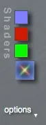
This group of tools relates to the Tree’s color mapping and shading mode. If the bottom tile of the tree has a single output and outputs an RGB or RGBA packed stream, the tree is treated as an RGB or RGBA tree (rather than a scalar tree using gradient coloring) and the shading options are adjusted accordingly. ArtMatic Voyager will treat these as RGBA trees as well.
Scalar trees are rendered using various mappings involving the main gradient and optional component values.
Auxiliary colors squares
Section titled “Auxiliary colors squares”The auxiliary color squares are color pickers for choosing the auxiliary colors used by some shading algorithms and various components. The number of auxiliary colors used is determined by the shading algorithm or the presence in the Tree of components using them.
Note: Auxiliary colors are global to a particular ArtMatic file. They are not stored in keyframes so they can’t be animated.
Depth cue color
Section titled “Depth cue color”The color used by Infinity depth cuing when ON and certain Components like 4:4 Alpha Fade or 2:3 Pict/Movie Overlay. The Depth cue color is always visible and available even when Depth Cueing is turned off. This color is used in RGB-based systems wherever the value infinity is encountered, like the outside of pseudo 3D objects and where the infinity gate component is used.
Aux color A
Section titled “Aux color A”Auxiliary color A (default: dark red) is used by several scalar tree procedural shaders (see below), and by RGB Multi mode for Tree extra outputs. A couple of components use this color as well, for instance 4:4 RGB * alpha or 1:3 Shaded plain color in certain modes.
Aux color B
Section titled “Aux color B”Auxiliary color B (default: green) is used by several scalar tree procedural shaders and by RGB Multi mode for Tree extra outputs. A couple of components use this color as well, for instance 4:4 RGB * alpha in certain modes. S:P Logic & Profiles uses Aux color B to shade the edges, for example.
Shading modes
Section titled “Shading modes”The icon below the color squares controls the current shading algorithm or Shading mode.
Note: Shading mode is global to a particular ArtMatic file, so it is not stored in keyframes and cannot be changed over the course of an animation.
Click the icon for a pop-up list of the color shading algorithms available (described below). The content of this menu changes, depending on the ArtMatic Tree output type.
For scalar trees (1 or 2 outputs) the shading algorithms are the following:
-
Cyclic clut:
Section titled “Cyclic clut:” This shader causes the colors to cycle throughout the value range. It applies a sine function whose output value is mapped to the gradient. Zero is mapped to the gradient’s central color. Clut stands for
 Color Lookup Table. -
Ceiled Linear clut:
Section titled “Ceiled Linear clut:” This shader uses a linear scale to map incoming values to the gradient. 0 is mapped to the gradient’s central color. The shader has a ceiling value above which incoming values are mapped to the rightmost color. There is also a floor value. Values below the floor are mapped to the leftmost color.
 -
Logarithmic clut:
Section titled “Logarithmic clut:” This shader is symmetrical about zero (i.e. -5 and +5 map to the same color) and the transition between becomes more gradual as the incoming values increase. Mathematically speaking, the logarithm of the absolute value of the tree’s output value is mapped to the gradient. 0 selects the leftmost color.
 -
Procedural A:
Section titled “Procedural A:”
- Base shader: logarithmic color shader,
- Auxiliary shading: pixel brightness determined by sine function,
- Auxiliary colors: none.
This shader combines logarithmic and cyclic shading. The Logarithmic Clut algorithm determines the pixel hues. ArtMatic then imposes shadows by applying a sine function to vary the pixel brightness. Where the sine function is 0, the image is black, and where the sine function is 1, the color is unchanged. The result is a sort of 3D cylindrical banding.
To make the most of this shader, use a two-input tile for either the final or the penultimate tile. Watch how the shading changes as you manipulate that tile’s inputs.
-
Procedural B:
Section titled “Procedural B:”
-
Base shader: logarithmic color shader,
-
Auxiliary shading: Aux. input 1 influences luminance, Aux. input 2 determines color shift.
-
Auxiliary colors: Aux color B.
This shader uses two auxiliary inputs from the tree to modulate an image calculated using a logarithmic shading algorithm. The first auxiliary input provides luminance information and the second provides a color shift using the second auxiliary color. Note: the first auxiliary color is ignored by this shader.
-
-
Procedural C:
Section titled “Procedural C:”
-
Base shader: logarithmic color shader,
-
Auxiliary shading: Auxiliary inputs one and two create a second image using a cyclic shader. Auxiliary input three controls the mix of the base and second image.
-
Auxiliary colors: none.
This algorithm calculates two intermediate images which are mixed together under the control of the third auxiliary input.
- The first intermediate image is calculated from the system using a logarithmic algorithm.
- The second intermediate image is calculated by feeding the first two auxiliary inputs into a sine-based shader.
- The third auxiliary input controls the interpolation (mixing) of the two intermediate images.
-
-
D:Log+Depth cueing+Color Filters:
Section titled “D:Log+Depth cueing+Color Filters:”
- Base shader: logarithmic color shader,
- Auxiliary shading: color filtering using auxiliary colors and inputs,
- Auxiliary colors: Aux color A and B,
- Global shading options: Depth Cueing.
This shader calculates a base image using logarithmic shading, turns on depth cueing (discussed later in this chapter) and uses the second and third auxiliary colors to filter the image. Two color filters (whose colors are provided by the second and third auxiliary colors) are calculated using two auxiliary values from the tree and applied to the base image. The filtering is done by multiplying the pixels of the filter with the pixels of the base image.
-
E:Linear+Depth cueing+Lights:
Section titled “E:Linear+Depth cueing+Lights:”
- Base shader: logarithmic color shader,
- Auxiliary shading: color filtering using auxiliary colors and inputs,
- Auxiliary colors: Aux color A and B,
- Shading options: Depth Cueing.
This shader is based on linear shading and operates similarly to shader D, except that the auxiliary color images are combined with the base image using addition, rather than multiplication. This shader also turns on depth cueing.
-
F:Linear+Directional Lights:
Section titled “F:Linear+Directional Lights:”
- Base shader: linear color shader,
- Auxiliary shading: directional lights controlled by the system’s last vector function plus black shadows to emphasize lighting direction.
- Auxiliary colors: Aux color A and B.
This shader creates directional lighting effects. The last vector function (i.e. the last function with two outputs) of the Structure Tree provides direction information for directional lights used to shade the image. A primary white light is shined on the surface while lights of the three auxiliary colors are shined from different directions. Black shadows are provided which emphasize the lighting effect.
-
G:Linear+3 Lights:
Section titled “G:Linear+3 Lights:”
- Base shader: linear color shader,
- Auxiliary shading: none specified.
- Auxiliary colors: Aux color A and B.
This shader is based on linear shading. Three pre-defined slots from the structure tree are used to provide lighting information using three auxiliary colors. The rules for determining which auxiliary inputs are used are complex.
If there is a three-input component, its inputs are used to add the auxiliary colors. If there is no three-input component, the last three inputs on the tree are used. If the auxiliary colors are all black, then the image will be identical to one shaded with the ceiled linear clut.
Tip: To see how this shader works, use an all black gradient and note the effects of changing the auxiliary colors.
-
H:Global Shade+3 Lights:
Section titled “H:Global Shade+3 Lights:”
- Base shader: linear color shader,
- Auxiliary shading: aux. inputs provide shading and lighting information,
- Auxiliary colors: Aux color A and B,
- Shading options: Global Shade On. This is another complex shader based on linear shading.
The Global Shade option (discussed later in this chapter) is turned on, which uses an auxiliary input to control the luminance (brightness) of the image’s pixels. The final component’s output provides global illumination multiplied against the linear-shaded image. Three auxiliary colors provide additional lighting.
Tip: For many structures, this can yield dramatic three-dimensional effects especially when the last component in the tree is the derivative
(dx)function. -
I:Global Shade + Lights + Depth Cueing:
Section titled “I:Global Shade + Lights + Depth Cueing:”
- Base shader: linear color shader,
- Auxiliary shading: aux. inputs,
- Auxiliary colors: Aux color A and B,
- Shading options: Depth cueing on.
This is another complex shader based on linear shading. It uses the last vector output function to provide depth cueing information, and two other auxiliary inputs which control the application of auxiliary colors two and three.
-
Linear Clut (Zero Based):
Section titled “Linear Clut (Zero Based):”
This shader is essentially similar to the linear shader, but maps zero to black and uses a normalised range, so that 1 gets mapped to white.
-
Balanced Log Clut:
Section titled “Balanced Log Clut:”
Balanced Log performs logarithmic gradient mapping using the gradient’s colors for values greater than 0, and complementary colors of the gradient for values less than zero. This is a variant of the ‘standard’ Logarithmic Clut shader, which uses the same colors for positive and negative values.
This shader is especially useful when using ArtMatic to design sounds, as it is very easy to see that positive and negative values are balanced (which is important for sound). Sounds that are out of balance suffer from DC Offset and will often result in clicks and distortion.
-
Geographic Clut:
Section titled “Geographic Clut:”
Geographic Clut is a shader that aids artists designing DF fields or terrains for ArtMatic Voyager. This mode clearly shows the boundary between the inside and outside (shaded with blue shades evoking underwater depth) of a DF volume, or the elevations under sea level (at zero) for terrain modeling.
ArtMatic Geographic Clut uses hard-coded colors to represent specific elevations. This mode is also available with RGBA trees.
For RGB or RGBA trees (which includes packed RGBA output trees) the shading algorithms are the following:
-
RGB Alpha (Main Out):
Section titled “RGB Alpha (Main Out):”
RGB Alphadoes no additional image processing. Most of the time, this is the shader you will use when creating RGB-based graphics. When a tree has three outputs, they directly provide the Red, Green and Blue channels of the RGB image. If there is a fourth output, its content is treated as an alpha channel that modulates opacity. A checkerboard pattern is used for transparent regions. If you don’t want an alpha channel, you can either:- use the mode RGB Multi mode
- add a
3:3tile to the end to convert to pure RGB (no alpha) - add a
4:4tile “Alpha scale and offset” to zero the alpha scale and set the offset above 1 to ensure total opacity.
NOTE: When rendering a movie with an alpha channel, make sure to select a codec compatible with alpha channels.
-
RGB Density (Main Out):
Section titled “RGB Density (Main Out):”
This shader is similar to RGB Alpha but turns any alpha value above zero to fully opaque. It is suited for DF color texturing when one needs to preview the colors but still have a clue about the exterior of the object that will be fully transparent in this mode.
-
Geographic Clut (Main Out)
Section titled “Geographic Clut (Main Out)”
Geographic clut creates a 3D topographic map where the fourth output of the tree provides elevation data and where the colors are provided by the built-in geographic clut. The first three outputs of the tree are ignored. So, it is often used while fine-tuning the system alpha or elevation output.
Alpha channel/elevation values below zero will be shaded with blue shades evoking underwater depth. For DF modeling this mode shows clearly the boundary between the inside and the outside of a DF volume.
In addition to elevation color mapping, this shader uses the terrain derivative to bump-shade the surface for increased clarity. The ‘Bump gain’ tool described below controls the bump shading amount. This shader is more computationally-intensive since calculation of a system’s derivative requires several Tree evaluations.
-
RGBA Bump (Main Out):
Section titled “RGBA Bump (Main Out):”
The tree’s RGB output is lighted/textured using the derivative of the fourth output (bump shading). Negative values will be shaded with bluish hues, getting darker when the distance to zero increases. This shader provides a sense of how a four-output system will appear in ArtMatic Voyager when used as a colored terrain (where the first three outputs will be treated as color and the fourth as elevation). It is also suited for DF object previsualisation, as the exterior zones are below zero and the shades will give a sense of the Distance Field itself.
If the tree has only 3 outputs, a derivative is calculated from a mix of RGB values. The ‘Bump gain’ tool described below controls the bump shading amount.
This shader can also create dramatic 3D-like textures. While the Geographic Clut gives an accurate portrayal of the elevations created by the ArtMatic system, the Geographic Clut ignores the color information embedded in the ArtMatic system.
The RGB+Alpha Bump shader gives you an idea of what the elevation map will look like when colored with the RGB information embedded in the system. This shader is more computationally-intensive since calculation of a system’s derivative requires several Tree evaluations.
-
RGBA Multi:
Section titled “RGBA Multi:”
In this mode, the alpha channel is ignored for the first output tile. Additional outputs will be composited into the overall image using the following rules:
- Scalar (single out) values will be shaded in additive mode with Auxiliary colors coloring the output.
- RGB (3 outs) colors will be shaded in additive mode.
- RGBA (4 outs) values will be composited as an alpha layer; that is, the alpha value of the component will control the blending of the color.
RGB multi is a fast way to compose several alpha layers over the first output that will be treated as an opaque background. It can also be used to render an RGBA system in opaque mode when the alpha channel is unwanted.
-
RGBA Bump (Multi Out):
Section titled “RGBA Bump (Multi Out):”This shader is similar to RGB Bump but can handle multiple RGBA outputs. It is particularly useful for dual-shaded DF objects used in Voyager, such as:
- Opaque + Light
- Opaque + Transparent
- Opaque + Transmissive
-
Shading Options Menu (pop-up)
Section titled “Shading Options Menu (pop-up)”In addition to the color shading algorithms, there are two powerful shading options: Depth cueing and global shading. Depth cueing provides fog and distance effects, and global shade provides lighting and shadow control. Both of these options can be assigned either automatically by ArtMatic or manually by the user. These options are accessed via the Shading Options pop-up menu.
Click the menu to open the pop-up list with various shading and rendering options.
-
Depth Cueing Off:
-
Depth Cueing Small:
-
Depth Cueing Medium:
-
Depth Cueing Strong: Depth cueing simulates the color-filtering effect of the atmosphere (the same effect that causes distant objects to appear faint). Depth cueing works by assigning the Depth cue color color according to a depth/distance evaluation. By default, ArtMatic picks the component in the tree associated with distance (generally the first auxiliary input). This assignment can be manually overridden (as explained below). This color is superimposed on the image in relation to the depth/distance. As the distance increases, so does the brightness and opacity of the depth color. ArtMatic provides direct manipulation of depth cueing which can be used for both distance and purely decorative effects.
For more control over depth cuing you can alternatively use the 4:4 Alpha Fade tile where the fourth input will drive depth cuing.
-
Global Shade Off: Turns off Global Shade.
-
Global Shade On: Another shading option is Global Shading (or shadowing) that can be turned on via the options menu. Global shading creates light and shadows in the image by modulating the luminance (brightness) of the image pixels. Where the shading component generates low values, the image will be dark (shadowed), and where it generates large values, the image will be brighter. As with depth cueing, you can choose the component that provides the shadows (global shading) as described below.
For more control over shading you can alternatively use tiles like 4:3 w Multiply and Illumination to implement shading within the tree. Note: The global shading glyph is the small marking in the icon’s lower-right corner.
-
Component sets Depth: The selected tile will be used to provide the Depth information.
-
Component sets Shade: The selected tile will be used to provide the Shade information, usually a derivative component. A small shaded glyph is used to indicate components that have been manually assigned.
Restoring automatic shade/depth control.
Section titled “Restoring automatic shade/depth control.”If you have used the
Component Sets DepthorComponent Sets Shadecommands and want ArtMatic to restore its automatic depth/shading choice, select theFog and Shade Automaticitem from the shading options pop-up menu. Note thatFog and Shade Automaticmay have a check mark even if depth and shading are turned off. The check mark merely indicates that if shading/depth are turned on that ArtMatic will choose the components automatically. -
Evaluate only for colors: This option is only relevant for systems to be used by ArtMatic Voyager. Turn this option on for any tile that should only be evaluated by ArtMatic Voyager during the color texture evaluation phase. This can greatly optimize rendering time by avoiding texture and color computation when unneeded.
For example, when designing RGB+Alpha trees that provide both the elevation map and the color texture to ArtMatic Voyager, set the color texturing part to “evaluate only for colors”. Voyager will ignore tiles that have this option set when calculating the elevation map. If possible, put all tiles used for generating the color texture in a compiled tree and apply this option to that single compiled tree tile.
-
Fog and Shade Automatic: The usual state, where ArtMatic will choose which tile provides Depth Cueing automatically.
-
Bump gain
Section titled “Bump gain” RGB Bump (Main Out) and Geographic Clut use the Tree elevation or alpha value to bump-shade the result implicitly. The Bump gain button lets you slide the amplitude of this bump shading. It is often quite useful to have a better grasp of terrain relief features or the DF field derivative.
For final renderings, we recommend using custom shaders where the derivative is shaded using the Structure Tree components to have better control of the bump shading function (instead of relying on RGB Bump mode). Examples of customized advanced bump shading techniques can be found in the Libraries/Textures/Shaded Surfaces/ folder.
Parameter Area
Section titled “Parameter Area”
Parameter grid options
Section titled “Parameter grid options”
This pop-up turns on/off various grid modes to restrict the parameter settings to the selected grid.
Options:
- No parameter grid,
- Integer Grid,
- Snap Grid (closely spaced grid),
- Pi/4 angle Grid (this restricts rotation and other angle-based parameters to increments of 45 degrees),
- Pi/6 angle Grid (this restricts rotation and other angle-based parameters to increments of 30 degrees).
Randomize colors & shaders
Section titled “Randomize colors & shaders”
Mutates the active gradient and the active Shading mode.
Randomize All
Section titled “Randomize All”Key Command: $

Randomizes all of the structure’s function assignments, parameter values, and color assignments. Control + click randomizes the entire structure tree as well as the function assignments. Tiles whose parameters are completely locked are protected from Randomize All.
Randomize Parameters
Section titled “Randomize Parameters”
Randomizes the parameters of all unlocked tiles. Repeatedly clicking this tool is one way to explore the possibilities of a particular system. The parameter locks can be used to prevent randomization of a particular parameter.
Mutations Explorer Dialog
Section titled “Mutations Explorer Dialog”
Invokes the Mutations Explorer dialog. The Mutations Explorer is one of ArtMatic’s most powerful tools, using genetic algorithms to generate mutations, while your choices take the role of natural selection.
It allows you to quickly and easily explore the huge Parameter Space of ArtMatic systems and mutate the current ArtMatic Structure Tree algorithm by randomly mutating its tile functions.
When the Mutations Explorer first opens, the current canvas image is the parent (the large image in the upper-left). Clicking the parent generates a new set of mutations. ArtMatic creates mutations by randomizing unlocked parameter values, the gradient and/or function assignments (depending on the selected options). Clicking any mutation (any child), makes that mutation the new parent. If the auto-mutate option is turned on, clicking any mutation makes that child the parent and generates a new set of mutations.
The Mutate (dice button) triggers a new set of mutations. Interesting mutations can be stored in the Keyframes using the Add or Replace Keyframe buttons. Clicking the OK icon button closes the dialog and validates the current state of the Tree.
Mutation rate: The mutation rate slider controls the mutation probability. High values will let you explore a large region of parameter space. Low values are often used to fine-tune a system or to find small variations in very sensitive systems like fractals. ‘Locked’ parameters won’t be mutated so you can use this property to protect certain parameters from mutations. Flow controllers like Iterations and Recursions parameters are not mutable, even unlocked.
Explore modes:
Several strategies are provided to explore the Parameter Space:
- Cumulative: The default mode accumulates mutations sequentially. The distance to the original point in the P-space increases row by row from the top left.
- Points cloud: The Points cloud mode explores a region of random points around the current state in parameter space. The distance to the original point in the P-space increases proportionally to the 2D distance with the top left thumbnail.
- Random path: The Random path mode uses a continuous random path within the parameter space to display the mutations. The distance to the original point in the P-space increases row by row from top left.
Mutate function type:
This checkbox is available in cumulative mode only. When ON, mutations include algorithm changes and tile component changes. Use this to explore systemic variations. Note that changes of algorithm or tile component will invalidate all existing keyframes as the mathematics of the entire structure tree will have changed.
Keyframes Parameters
Section titled “Keyframes Parameters”
Invokes the Keyframes Parameters Envelope dialog that displays time curves for each active parameter of the currently selected tile. This dialog is available in ArtMatic Designer only when more than 2 keyframes exist. To create Keyframes visit the Timeline and Keyframes Area.
A, B, C, D Buttons (pop-up)
Section titled “A, B, C, D Buttons (pop-up)”These pop-up menus give you access to parameter-related functions and shortcuts for each used parameter:
- Publish parameters: The advanced user can “publish” parameters from the tree in the designer room even if they are located deep inside CTs. “Published” parameters will appear on top of the 6 parameters that the Explore room shows. “Published” parameters will also be directly accessible in ArtMatic Voyager for fine-tuning. Published parameters have a green lock icon or an orange lock icon if the parameter is locked.
- Unpublish:
Unpublish a published parameter. - Published parameters names…
Invokes a dialog that lets you rename the 6 (or less) published parameters. The published parameters should be renamed when the default generic parameter name is not informative enough in certain cases, especially when you plan to share the ArtMatic file with other users. These names should be set once the tree is stable enough as they can get lost in the editing process: Copy/paste won’t preserve published flags and names for example, and tree editing may mess up the order of the parameters and their names. - Send current value to all KF:
Sends the current parameter value to all keyframes. - Ramp full range:
Meaningful only when keyframes exist, this function ramps current parameter values from minimum to maximum in all keyframes. - Ramp from first to end:
Meaningful only when keyframes exist, this function ramps current parameter values from first KF value to last KF value in all keyframes. If they happen to be the same, this will make the parameter static over the animation. - Reverse time:
Meaningful only when keyframes exist, this function reverses the time of the parameter keyframes envelope. - Reset to default:
Lets you reset a particular parameter to its default value. - Reset All to default:
Lets you reset all of a tile’s parameters to their default values.
Parameter sliders (A, B, C, D)
Section titled “Parameter sliders (A, B, C, D)”Component’s parameters are modified using the parameter sliders. Each tile in a structure has from 0 to 4 parameters (settings). Each keyframe in a file can have different settings. To modify a tile’s current parameters, click on the tile then manipulate the parameter sliders. To see what a parameter controls, move the mouse over the slider and note the Tool Tips display. Drag a slider to change its value or option + click to make small changes.
In the “Design” room, the parameter sliders change the current tile’s values. The changes will be lost if you have keyframes and either change the current time or select a keyframe as the parameter value will then be derived from the animation keyframes. To store parameter changes in a keyframe, you may need to replace the current (or any) keyframe, unless the parameter is locked, in which case the current value applies to all keyframes. To access and edit the keyframe values in the Design room, click the Keyframes Parameters button to open the Keyframes Parameters Envelope dialog.
In the “Explore” room, the published parameter sliders will directly edit the keyframe values (if any), and the parameter envelope is displayed in the main window for direct editing of the entire set of values. Select first a keyframe to get the parameter value at that time, then any changes will be assigned to the keyframe without having to replace it.
Parameter Locks
Section titled “Parameter Locks”The parameter locks (found to the right of the parameter sliders) allow function parameters and component assignments to be locked to prevent them from being changed by operations such as mutation that normally change parameter values. When a parameter is locked its animation is disabled as well. When all parameters are locked, the tile itself can no longer be mutated.
To lock all tiles, shift + click any unlocked parameter. Locked parameters show the lock icon in red. This makes it possible to use the Mutations dialog to explore variations of only a few parameters. To unlock all tiles, shift + click any locked parameter.
Locking parameters and functions is a great way to explore ArtMatic systems. Parameter/function locking makes it possible to use mutations and the large die to explore subtle refinements. For example, you might have a system that uses a few tiles to provide the surface texture. You could lock all of the parameters and functions of the system except for the tiles that provide the texture and then use the big die or the Mutations window to discover new textures created by function mutation that affects only the few components that provide the texture.
Note: When parameters are locked, keyframe animation uses the last values assigned to the locked parameters when animating the system. As a result, any parameter changes stored between keyframes are ignored while the parameters are locked. The parameter changes are not lost, however; they are just ignored. When the parameters are unlocked, any parameter changes stored in the keyframes will be honored during animation. Parameter locking is intended for refined mutation control and for investigating how a particular parameter affects the system.
Parameter optional gradient
Section titled “Parameter optional gradient”Certain components use an indexed gradient directly from the built-in gradients library like 1:3 Indexed Gradient. This gradient is displayed for editing when such a component’s tile is selected and the button below may open the standard Gradient editing dialog if needed.
Parameter optional color
Section titled “Parameter optional color”Certain component parameters set an RGB color. This color pop-up is available when a component’s tile is selected and can be used to edit the 3 RGB values at once. For example - the 1:3 Set Constant tile sets a constant RGB color with its parameters.
Timeline and Keyframes Area
Section titled “Timeline and Keyframes Area”
This area is focused on Animation controls. It provides the Keyframes UI, the main timeline slider, and various buttons to control keyframes. Keyframes store not only all current Tree parameters, but also the current Canvas View Zoom and Position and the current Main Gradient. The animated sets of zoom and position stored in Keyframes constitute the “camera path”.
All components constituting the Tree can have their parameters animated, as long as they are not locked. ArtMatic creates animation by changing the system’s parameters over time, morphing the values from keyframe to keyframe. Various modes of parameter interpolation are available: they can be chosen inside the Keyframes Parameters dialog. The default uses Bezier curves to ensure smooth interpolation.
Sound can be used to modulate ArtMatic animations when they are rendered, and a soundtrack can be added or generated (using the sound algorithm last used on the Sound page) when rendering. Audio modulation is a powerful technique to use for creating video for music videos and multimedia compositions. To modulate ArtMatic animation with audio, audio input must be routed from the Global Input Matrix into the Structure Tree. See the Global Input Matrix section for more information about this topic.
Tip: Making global changes to all keyframes. Holding down the
shiftkey when performing many operations applies the operation to all of the ArtMatic tree keyframes. (These operations include: gradient selection, zooming and scrolling the canvas, and changing parameter values.)
Animation pop-up menu
Section titled “Animation pop-up menu”
The Animation menu provides the following:
- Animation & Camera setup…
a: Invokes the Animation setup dialog, which determines the animation duration, animation type and the camera movement. This dialog and its settings are covered in the Animation page. - Add Keyframe:
k - Replace Keyframe:
l - Delete Keyframe:
- Insert In-between Keyframe
i: Same functionalities as the corresponding buttons. - Guess Next Keyframe
g: Generates a keyframe that continues the motion of the previous keyframes. This command is only available when the last keyframe is selected and at least 2 keyframes are present. - Copy Camera Path: Copies the current camera path to the clipboard so that it can be pasted into another file.
- Paste Camera Path: Pastes a copied camera path onto the current system.
Time Slider
Section titled “Time Slider”This is the main slider that controls global ArtMatic Designer time. The time flows from 0 to the given duration. You can use the time slider even when no keyframes are present when the ArtMatic tree is using one of the time global inputs.
You can click + drag on the time slider to preview the animation in non-real time or simply click at a particular time to see a frame preview at that moment.
Keyframes thumbnails
Section titled “Keyframes thumbnails”Keyframes store all the current parameter values of the tree’s components, so they can be animated over time. They also store the current canvas view and the main gradient. The ArtMatic system’s keyframes will be mapped in time so that all the keyframes play back over the course of the animation. When just 2 Keyframes are present, the first represents the state of the system at time 0 and the second at time 1 (the end of the animation).
Keyframes are not limited to animation: they are often used to store interesting variations of the huge Parameter Space of ArtMatic Trees. Sliding the timeline will interpolate these parameters to let you discover more interesting points in the space of possibilities.
Click on any empty slot to store a new keyframe from the current Tree parameters. Clicking on a keyframe will select it. When selecting a keyframe, the Tree parameter variables stored in the keyframe will be copied to the current Tree, with the exception of parameters that were specifically LOCKED to not be animated.
The time slider will also reflect the particular time position of the selected keyframe and send this time information to Voyager when the Voyager hot link toggle is ON. In Explore room it will highlight the published parameter envelope value if the parameter has an envelope. Then you can modify the keyframe parameter directly in the envelope as well as with the parameter slider. Although you can edit the entire envelope, it is safer to move the highlighted parameter to see the results.
Command+Clickon a keyframe will replace it.Option+Clickon a keyframe will delete it.
Note: Keyframes thumbnails are not recomputed for every change you can make so they may become misleading in certain cases. To force a full keyframe redraw you can lock/unlock any parameter.
Key Command: Space Bar

Previews the current animation. The resolution adapts to the CPU load of the current Tree to keep the motion fluid. Unlike in earlier versions, the priority is given to frame rate to ensure at least 12 fps. Slow systems may play back very pixellated. The old small preview mode is gone but you can alternatively use the small animation preview provided by the Animation & Camera setup dialog that won’t change the resolution.
Even without keyframes,
playwill flow time so that time-sensitive or time-connected components will be animated as well.
Duration MSF
Section titled “Duration MSF”
The watch icon is used to set the animation duration. Click + drag left or right to change the duration. Duration is displayed in MSF format (minutes, seconds, frames).
Delete (Keyframe)
Section titled “Delete (Keyframe)”Delete the selected keyframe. Key Command: option + click any keyframe to delete it.
Insert (Keyframe)
Section titled “Insert (Keyframe)”Calculates a new keyframe that is halfway between the selected keyframe and the keyframe after it.
Add (Keyframe)
Section titled “Add (Keyframe)”Adds a new keyframe with the current Tree parameters. Shortcut: you can also click on the first blank keyframe to add a new keyframe.
Replace (Keyframe)
Section titled “Replace (Keyframe)”Replaces the selected keyframe with the current Tree parameters. You may also use command + click on a keyframe slot to perform the replacement.
Left Tool Buttons
Section titled “Left Tool Buttons”Open ArtMatic File
Section titled “Open ArtMatic File”
This button echoes the File->Open command and will prompt you to locate an ArtMatic file (.artm extension).
Save ArtMatic File
Section titled “Save ArtMatic File”
This button echoes the File->Save command and will either directly save the current scene if the file already exists or prompt you to set a name to save the ArtMatic file.
Render Pict to Screen
Section titled “Render Pict to Screen”
Renders the current scene fullscreen with Anti-Aliasing ON. Once the current image render is done, you may animate the system using the Space bar. The full screen animation preview is done at the preview resolution set in Preferences and won’t be changed for slow systems. Frame rate may vary with the CPU load of the ArtMatic Tree. When the animation mode is set to “free run loop” or the global input matrix is set to audio input, the fullscreen animation playback will loop forever. With fast ArtMatic Trees you can set the preview resolution to 1.
Render Image to File (cmd-R)
Section titled “Render Image to File (cmd-R)”
This button opens the Render Picture dialog that displays the settings used to render image file(s). Size pop-up and size fields: Common dimensions are provided by the Size pop-up menu. The numeric fields accept any entry up to 24000. Over 15K resolution, the rendering will be performed directly to disk and may take a while.
Formats:
Section titled “Formats:”-
PNG 8-bit per channel,
-
PNG 16-bit per channel:
PNG is a lossless widespread format and is recommended. Use the 16-bit version for printing and high quality graphics. It will solve any banding or quantization artifacts. -
TIFF: Save the image in 8-bit per channel,
TIFFformat (.tiff). -
PDF: Save the image in 8-bit per channel,
PDFformat (.pdf). -
JPG: Save the image in 8-bit per channel,
JPEGformat (.jpg).Note that jpg has no alpha channel. Use this for high-compression web applications.
-
HeightMap 1025 16-bit / 2049 16-bit:
Save the image inRAW, 16-bit per channel grayscale image. This is suited to store terrain elevation in 1025 and 2049 square format for 3D applications like Unity 3D. -
PNG HeightMap 16-bit:
16-bit per channel grayscale image of any size suited to store terrain elevation or high-quality texture channel for bump mapping in 3D applications. -
Render all keyframes: (checkbox)
When set ArtMatic will render one image for each stored keyframe. Keyframes can be used to store interesting variations of a given tree. In that case it may be quite useful to render the entire set instead of just the current image. -
4 by 4 anti-aliasing: (checkbox) Turn ON/OFF 16 samples per pixel rendering mode. Use it to improve quality for fractals and systems with a lot of high-frequencies.
Render Image File Path:
Section titled “Render Image File Path:” Click this button to set the image file path. By default the path is set to be in the same directory as the ArtMatic file. You don’t have to set it for every save as it will remember the output directory.
Note: No warning is given if you overwrite a file when saving without setting the path.
Render Animation (cmd-M)
Section titled “Render Animation (cmd-M)”
Click the Render Animation tool to render an animation. The file does not need keyframes to be animated. To stop a render, press the escape key.
Mode pop-up (movie or picture sequence) - The options are:
Movie:
ArtMatic Engine 8 uses AVFoundation to save animation in the .mov format. Possible codecs are:
-
H264 (no Alpha),
-
Apple ProRes 422 (no Alpha),
-
Apple ProRes 4444 (8-bit Alpha),
-
Apple ProRes 4444 (10-bit Alpha),
-
Apple ProRes 4444 will support alpha channels and the 10-bit version offers the best quality. H264 is more compressed and widely supported.
Note: Make sure you set the file path, as no warning is given if you overwrite a
.movfile. -
List of Images (png/tiff),
The “List” options render the movie frames as sequentially numbered image files (in either PNG for List of Pictures or TIFF for List of Tiff).Such sequences are recognized by most movie editing programs and by ArtMatic pict/movie inputs. Using image sequences is a good idea when performing a long render since nothing will be lost if the computer shuts down unexpectedly. (movies will likely be unplayable if the render is interrupted by anything other than the escape key).
Preset pop-up:
Section titled “Preset pop-up:”The preset pop-up provides a list of common frame size/frame rate combinations. Choosing a preset causes the format and fps fields to be filled in with the appropriate values.
- 4 by 4 anti-aliasing: (checkbox)
Turn ON/OFF 16 samples per pixel rendering mode. Use it to improve quality for fractals, systems with a lot of high-frequencies, or high-contrast graphics with fine details. Rendering time will be multiplied by 4 with this option ON.
Note: the default anti-aliasing is 2 by 2, (4 samples per pixel).
Render Animation File Path:
Section titled “Render Animation File Path:”
Click this button to set the animation file path. By default the path is set to be in the same directory as the ArtMatic file. You don’t have to set it for every save as the the output directory is retained.
Note: No warning is given if you overwrite a file when saving without setting the path.
Save Sound File
Section titled “Save Sound File”
Available in Listen room, this button will save the sound file produced by the current Tree. The file is AIFF and uses 44.1 kHz for its sampling rate. Note that when rendering the sound to file, the internal maths are more precise than in real-time playback and the sound may slightly differ.
Voyager Hot Link (toggle)
Section titled “Voyager Hot Link (toggle)”
This button lets you turn ON and OFF the Hot link with ArtMatic Voyager. When hot link is ON, changes in parameters and Structure Tree will be communicated to Voyager through Apple Events.
When Voyager receives such an event a pop-up floating preview shows the 3D rendering. This makes the design of terrains, textures and the construction of volumetric objects much more friendly as you can see the 3D rendering interactively, whilst adjusting parameters. Transport time information is also transmitted when using the time slider or selecting a keyframe.
When the tree is structurally modified, ArtMatic will send the new tree to Voyager using a temporary file, so the original is preserved. (Unless you save the file in ArtMatic or the Voyager scene in Voyager, you can always go back to the original).
Changes in ArtMatic globals, such as optional colors and gradient colors are not transmitted automatically. However, they will be transmitted if you turn OFF and immediately ON the hot link: (when turning ON the entire file is sent as explained above for structural changes).
Hot Link Notes:
Section titled “Hot Link Notes:”-
Using the
Hot Linkfeature (alongside published parameter changes) of the ArtMatic Tree within Voyager may lead to inconsistent situations. -
If you use the ArtMatic Quick Edit parameter and shaders inspector, and have changed the ArtMatic tree parameters inside Voyager, Reload the file in ArtMatic again. Reloading will update ArtMatic with these changes. Otherwise, if the ArtMatic tree is modified, the changes will be undone.
-
If you use “save as” in Voyager, that will change the ArtMatic file path (ArtMatic files are stored within the Voyager file bundle), meaning the one opened in ArtMatic will no longer point to the right file location and will still point to the original.
The solution is to reload the ArtMatic file into ArtMatic from Voyager after “save as” to make sure you edit the correct file.
Hot Link Troubleshooting:
Section titled “Hot Link Troubleshooting:”If communication doesn’t work as expected, there are a number of things to double-check:
- Is the Voyager hot link ON?
- Is the current ArtMatic file pointing to the right one? To be sure, re-open the file from ArtMatic Voyager. Do the same if you have changed the file name in either software application.
- Make sure ArtMatic and Voyager versions are compatible and are the only ones running. Use both CTX or 7.5/4.5 together and don’t mix versions. If various versions are running simultaneously, the OS may send the Apple Event to the wrong application.
- As a last resort, the OS Apple Events system is probably corrupted, and rebooting the computer usually fixes the problem.
Component Descriptions
Section titled “Component Descriptions”Designer contains a library of components. Each is a module you can patch together in the structure tree. They all have a fixed number of inputs and outputs. When you click on a component in a “tree”, a pop-up appears showing all the other components of the same Input/Output type. Click below for the component descriptions:
- ArtMatic 1 in 1 out components.
- ArtMatic 1 in 2 out components.
- ArtMatic 1 in 3 out components.
- ArtMatic 1 in 4 out components.
- ArtMatic 2 in 1 out components.
- ArtMatic 2 in 2 out components.
- ArtMatic 2 in 3 out components.
- ArtMatic 2 in 4 out components.
- ArtMatic 2 in 5 out components.
- ArtMatic 3 in 1 out components.
- ArtMatic 3 in 2 out components.
- ArtMatic 3 in 3 out components.
- ArtMatic 3 in 4 out components.
- ArtMatic 4 in 1 out components.
- ArtMatic 4 in 2 out components.
- ArtMatic 4 in 3 out components.
- ArtMatic 4 in 4 out components.
Reminder: ArtMatic Designer is an “open” system. There is no limit to what it can be used for. With Compiled Trees in Designer, you can design your own custom functions that will further enrich the huge toolbox of the ArtMatic Engine.
Video Tutorials
Section titled “Video Tutorials”U&I University provides video tutorials on ArtMatic Designer and ArtMatic Voyager. Take a look at our Official YouTube Channel for the latest episodes. We hold live Q&A sessions weekly. Make sure to check the topic schedule. Here are the videos so far:
- Designer CTX 1.0 - User Interface Basics
- Designer CTX 1.0 - Tile Tree Components 1
- Designer CTX 1.0 - Tile Tree Components 2
- Designer CTX 1.0 - Tile Tree Deconstruction (Making a Face)
- Voyager CTX 1.0 - User Interface Basics
- Voyager+Designer CTX 1.0 - Depth Field 3D Objects Basics 1
- Voyager+Designer CTX 1.0 - Depth Field 3D Objects Basics 2
- Voyager+Designer CTX 1.0 - Creating Depth Field 3D Objects
- Voyager CTX 1.0 - Sprites Basics
- More to come!